
Electrochemical ultra-capacitor taking lithium ion battery electrode material as cathode
A supercapacitor, electrochemical technology, applied in the field of capacitors, can solve the problems of poor cycle life, difficult to popularize and apply, and expensive Ru and Ir
- Summary
- Abstract
- Description
- Claims
- Application Information
AI Technical Summary
Problems solved by technology
Method used
Image

Examples
Embodiment 1
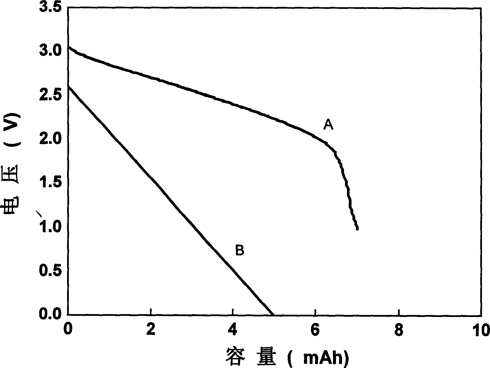
[0019] Negative electrode Li prepared by solvent dispersion method 4 Ti 5 o 12 Material. First, the titanium compound and the lithium compound are uniformly dispersed and ground with a solvent, and then calcined at 300-1000° C. for 6-48 hours to obtain a product with a particle size of 200 nm. The composition of the negative electrode of the capacitor is according to Li 4 Ti 5 o 12 : conductive agent: binder = 65: 25: 10 weight ratio mixing slurry, then control a certain coating thickness, evenly coated on the aluminum foil current collector. The activated carbon used as the positive electrode material is commercial activated carbon, and the slurry is mixed according to the weight ratio of activated carbon: conductive agent: binder = 80: 10: 10, and then coated on the aluminum foil current collector with a certain thickness. In this embodiment, the coating thickness of the positive and negative electrodes is controlled with the negative electrode material utilization rat...
Embodiment 2
[0021] According to the coating requirements of positive activated carbon in Example 1, a symmetrical 7# (φ10*38L, mm) activated carbon capacitor was assembled, and its diaphragm and electrolyte were the same as in Example 1. The working range of the system is 0V-2.6V, and the discharge curve of the capacitor is as follows figure 1 shown. The discharge capacity is 5Ah, and the average working voltage is 1.3V. The charge and discharge rate characteristics and cycle performance are shown in Table 1.
Embodiment 3
[0023] Negative electrode Li prepared by solid-phase synthesis method 4 Ti 5 o 12 Material. After the titanium compound and the lithium compound are ground uniformly, they are calcined at 300-1000° C. for 6-48 hours to obtain the product. The material has a particle size of 1 μm. Prepare capacitor negative pole and positive pole according to the slurry mixing and coating method in embodiment 1, control negative pole utilization rate 60% equally, make 7# capacitor (φ 10*38L, mm), its diaphragm and electrolytic solution are all the same as embodiment 1. Its characteristics are detailed in Table 1. The system of Example 3 has a specific energy of 3.3Wh / kg, a capacity of 7.6Ah when charged and discharged at 5C, and a capacity of 3.0Ah when charged and discharged at 100C, and a capacity retention rate of 87% after 3000 cycles.
PUM
| Property | Measurement | Unit |
|---|---|---|
| Particle size | aaaaa | aaaaa |
Abstract
Description
Claims
Application Information