High optical efficiency low working voltage cold cathode fluorescent lamp

A cold cathode fluorescent lamp, working voltage technology, applied in the direction of fluorescent, discharge lamp, gas discharge lamp, etc., to achieve the effect of low working voltage, improved luminous efficiency, and prolonged lamp life

Inactive Publication Date: 2005-10-19
SOUTHEAST UNIV
View PDF0 Cites 2 Cited by
  • Summary
  • Abstract
  • Description
  • Claims
  • Application Information

AI Technical Summary

Problems solved by technology

Therefore, a large part of the co

Method used


Image

  • High optical efficiency low working voltage cold cathode fluorescent lamp
  • High optical efficiency low working voltage cold cathode fluorescent lamp

Examples


Example Embodiment

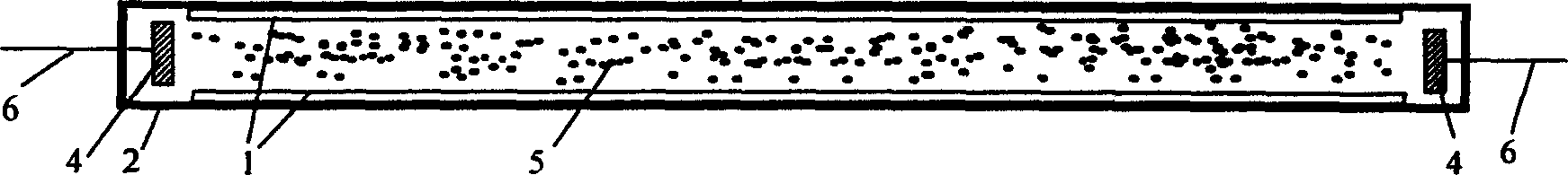
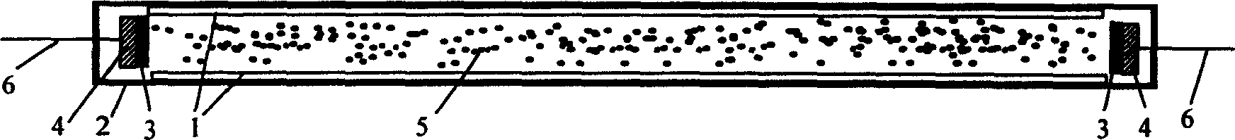
[0013] The cold-cathode fluorescent lamp with high light efficiency and low working voltage of the present invention is to place a pair of metal discharge electrodes whose surface is coated with a medium layer 3 of a material with a high secondary electron emission coefficient at the two ends of the fluorescent lamp glass tube 2 whose inner wall is coated with fluorescent powder 1 4. The discharge electrode 4 is drawn out of the glass tube through the metal lead electrode 6, and the inside of the lamp tube is filled with a discharge gas composed of inert gas helium, or neon, or argon, or xenon, or their mixed gas, and mercury metal. . The dielectric layer 3 made on the surface of the metal discharge electrode 4 is a magnesium oxide or aluminum oxide dielectric layer. Before the metal discharge electrodes of traditional cold cathode fluorescent lamps are sealed and made into tubes, methods such as vacuum coating, or chemical coating, or coating, or impregnation, followed by dry...


PUM

PropertyMeasurementUnit
Thicknessaaaaaaaaaa

Abstract

A high light efficiency and low working voltage cold-cathode fluorescent lamp relates to that used in LCD back light source, electric illumination and ordinary illumination. A couple of metallic discharge electrodes coated with dielectric layers high secondary electronic emit factor material on the surface are put at both ends of a fluorescent tube coated with phosphor powder on the internal wall and is led out of the glass tube by a metal lead, the glass tube is charged with discharge gas composed of inert gas He, Ne, Ar or Xe or their mixed gas and Hg.

Description

technical field [0001] The invention relates to a cold-cathode fluorescent lamp used in liquid crystal display backlight, electrical lighting, daily lighting and the like, in particular to a cold-cathode fluorescent lamp with low working voltage and high luminous efficiency. Background technique [0002] Cold Cathode Fluorescent Lamp (CCFL) is a new type of light source that does not require cathode filament heating, and the tube diameter can be made very thin (generally below 10mm, such as 1.8mm). The electrons and ions required for gas discharge in CCFL are produced by gas The ionization process and the secondary emission from the electrode constitute, which is different from the gas discharge formed by the hot cathode fluorescent lamp (HCFL) through thermionic emission of the hot cathode. Cold cathode fluorescent lamps are widely used in places where the volume of the light source is particularly small due to their small outer diameter and no...

Claims


Application Information

Patent Timeline
IPC IPC(8): H01J61/00H01J61/06H01J61/12H01J61/42
Inventor 张晓兵英达正
Owner SOUTHEAST UNIV
Why Eureka
Try Eureka