Low pressure olefin recovery process

An olefin and ethylene technology, applied in the field of olefin recovery, can solve problems such as explosion and nitrogum instability, and achieve the effects of low capital cost, low energy consumption, and less equipment

Active Publication Date: 2006-01-04
KELLOGG BROWN & ROOT INC
View PDF1 Cites 26 Cited by
  • Summary
  • Abstract
  • Description
  • Claims
  • Application Information

AI Technical Summary

Problems solved by technology

Nitrogen is unstable and will explode when s

Method used


Image

  • Low pressure olefin recovery process
  • Low pressure olefin recovery process
  • Low pressure olefin recovery process

Examples


Embodiment 1

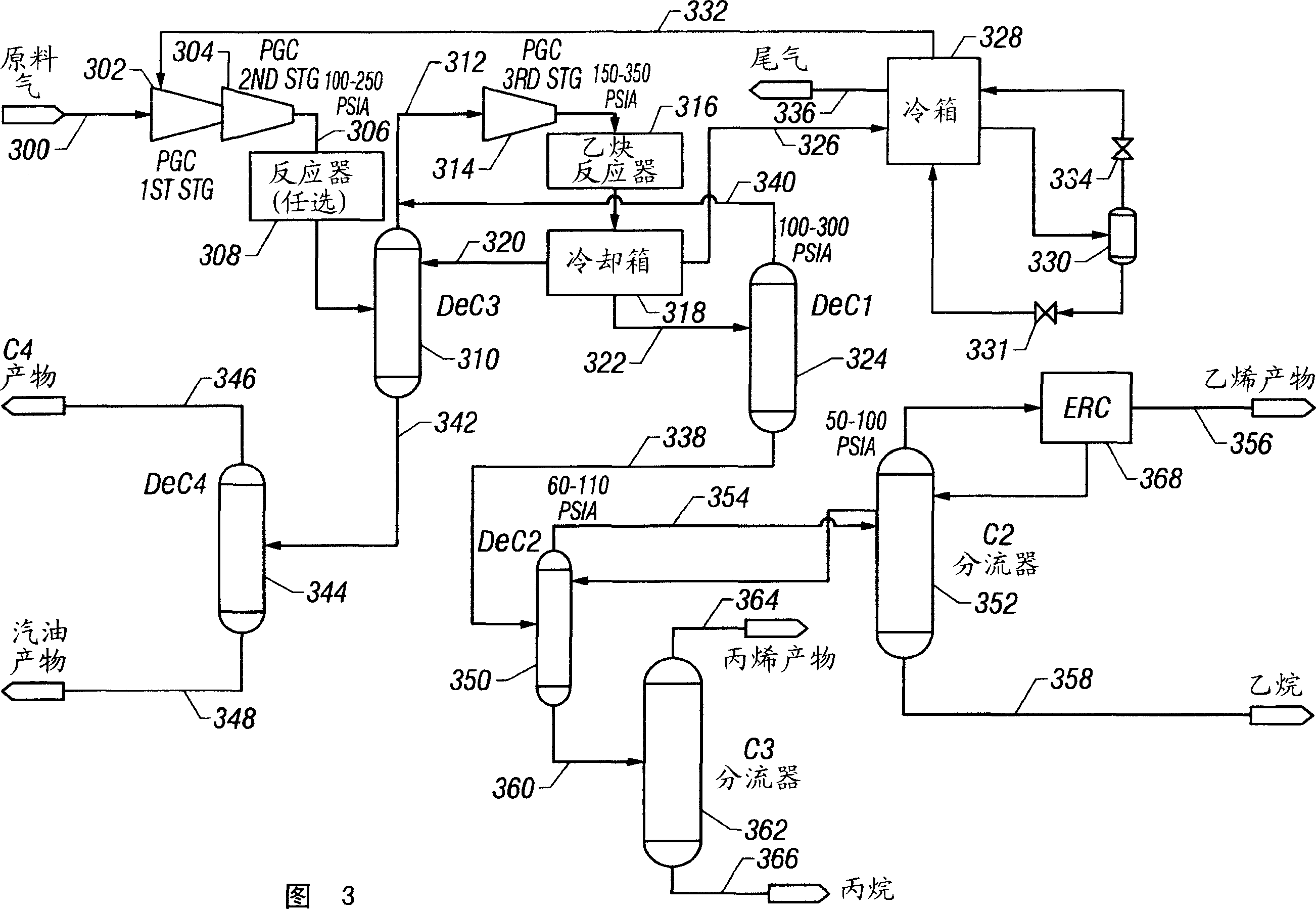
[0050] Embodiment 1: adopt such as on commercial Aspen simulator Figure 8A and 8B ("FIG. 8") shows a simulation of the embodiment shown in FIG. 3 with selected pressures (oval icons) and temperatures (hexagonal icons) as indicated. The feedstocks were in the form of gaseous and liquid streams whose compositions are shown in Table 1.

[0051] components

Steam raw material (mol%)

Liquid raw material (mol%)

H 2

6.4

0.0

N 2

0.4

0.0

CO 2

0.1

0.0

h 2 S

0.2

0.0

CH 4

5.8

0.0

C 2 h 4

13.3

0.3

C 2 h 6

2.5

0.1

C 3 h 6

20.1

1.8

C 3 h 8

6.4

0.7

1,3-butadiene

0.1

0.0

1-butene

10.0

3.0

Isobutane

9.2

2.2

n-butane

2.9

1.0

C 5+

17.6

90.6

h 2 o

5.0

0.3

Total...

Embodiment 2

[0054] Embodiment 2: In this embodiment, adopt on commercial Aspen simulator Figure 9A and 9B ("Fig. 9") shows the simulated graph, under the selected pressure (oval icon) and temperature (hexagonal icon), as in Example 1 for Figure 7 The embodiment shown was simulated. The separator bowl 330 is replaced with an absorber 782 . The partially condensed stream withdrawn from cold box 728 is sent to absorber 782 which has only a few trays and no condenser or reboiler so the additional cost compared to separator drum 330 is minimal. The vapor stream 726 exiting the secondary demethanizer feed separator (-70.6°C / -95.1°F drum) is further cooled by cold box 728 to exactly -100°C (-148°F), whereas in Example 1 It is -126°C (-195°F). This partially condensed stream is then sent to the bottom tray in absorber 782 . Ethane liquid stream 784 withdrawn from C2 splitter bottom 758 passes through exchanger 786 in cold box 728 (see Figure 7 ) is cooled to -100°C (-148°F). Mass transf...


PUM


Abstract

A low-pressure olefins recovery process and plant are described. The feed gas 300 is compressed 302, 304 and distilled 310 at a primary distillation pressure. The overhead stream 312 is chilled 318 at a pressure less than 30 kg/cm 2 (430 psia) to partially condense the overheads. The primary distillation tower 310 is refluxed with at least a portion of the condensate 320. The overhead vapor is further chilled 318 and partially condensed and the condensate 322 is fed to a demethanizer 324. The remaining vapor 326 is cooled in a cold section 328 and the resultant liquid is phase-separated 330 and expanded 331, 334 to provide refrigeration for the cold ssection. The expanded vapor 332 from the cold section is recycled to the process gas compressor. The bottoms streams 338, 342 from the primary distillation zone and the demethanizer are fractionated into respective streams consisting essentially of ethylene 356, ethane 358, propylene 364, propane 366, C 4 's 346, and C 5+ 348.

Description

technical field [0001] The present invention relates to an improved method for recovering olefins, in particular to such a method for recovering olefins, which adopts a low-pressure front-end distillation unit equipped with a low-pressure cooling box, a low-pressure deethanizer and a low-pressure demethanizer to make the recovery of olefins The number of equipment is minimized, thereby reducing the capital cost of equipment. Background technique [0002] The feed gas for olefin production comes from catalytic reactors and / or thermal cracking furnaces well known in the art, such as SUPERFLEX from Kellogg Brown & Root TM method, catalytic method for cracking methanol, deep catalytic cracking method, FCC reactor, etc. Feed gas containing olefins must be processed to separate and recover the olefins from various quantities of other gases, which may include hydrogen, methane, ethane, propane, butane, and pentane and higher hydrocarbons. Feed gas may also contain pollutants such...

Claims


Application Information

Patent Timeline
IPC IPC(8): C07C7/11C07C7/04C07C7/00
CPCF25J2270/90F25J2205/50C10G70/043F25J2245/02F25J2210/04F25J3/0238C07C7/005F25J2230/30F25J2270/08F25J3/0219C07C7/04F25J3/0252F25J2215/62F25J2270/02F25J2210/12Y02P30/40F25J2205/04C07C11/06C07C11/04
Inventor V·K·维尔马胡际川
Owner KELLOGG BROWN & ROOT INC
Why Eureka
Try Eureka