Plane capillary core evaporimeter with fin for CPL

A technology of capillary core and heat sink, which is applied in the direction of instruments, instrument cooling, and instrument parts, etc., can solve the problems of reducing system heat transfer efficiency, insufficient system liquid supply, increasing heat transfer thermal resistance, etc., to improve heat transfer Efficiency, ease of use, and the effect of reducing contact thermal resistance

Inactive Publication Date: 2006-01-25
HUAZHONG UNIV OF SCI & TECH
View PDF0 Cites 25 Cited by
  • Summary
  • Abstract
  • Description
  • Claims
  • Application Information

AI Technical Summary

Problems solved by technology

[0003] CPL usually uses a tube evaporator. The disadvantages of the tube evaporator are: ①In order to use the tube evaporator for heat dissipation, a cold plate must be attached to contact the cold plate with the load surface to achieve the purpose of heat dissipation. This method increases The heat transfer resistance is reduced, and the heat transfer efficiency of the system is reduced; ② After the liquid enters the central channel of the evaporator, it flows into the capillary core in the radial direction and evaporates, and the generated steam flows into the channel of the tube wall, and then flows into the steam pipe through the end of the channel. When the heat load of the system changes sharply,

Method used


Image

  • Plane capillary core evaporimeter with fin for CPL
  • Plane capillary core evaporimeter with fin for CPL
  • Plane capillary core evaporimeter with fin for CPL

Examples


Embodiment Construction

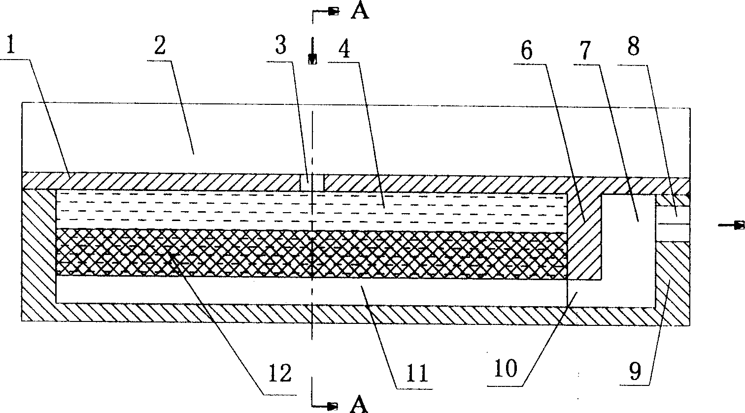
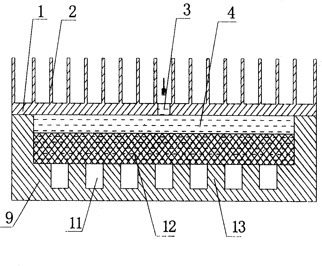
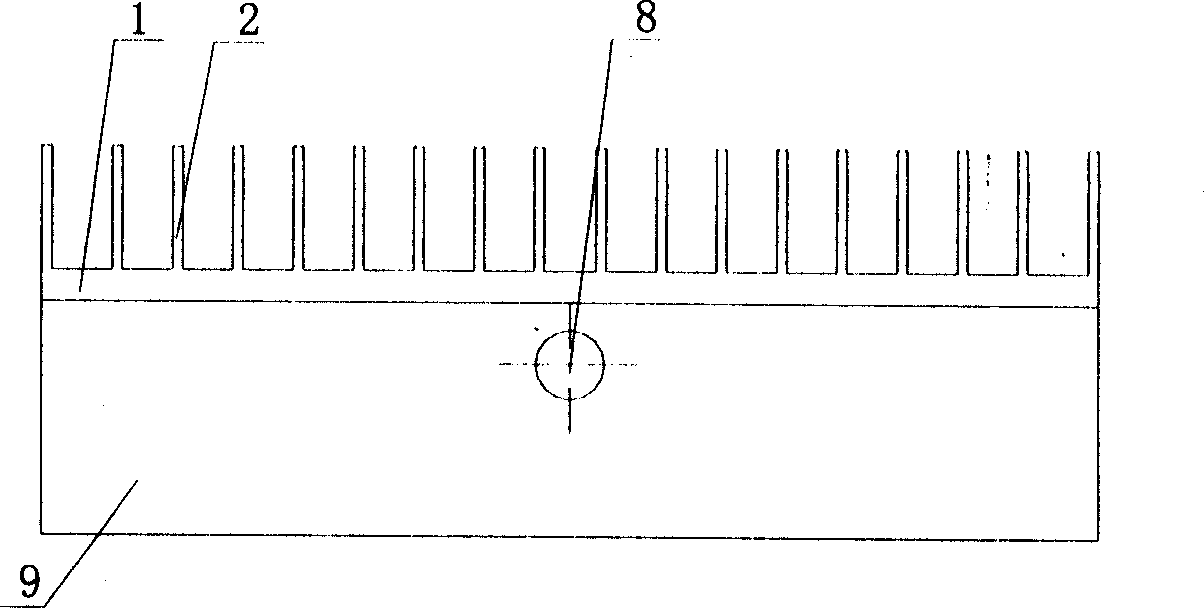
[0021] Depend on Figure 1 to Figure 7 As shown, the present invention includes a base 9 , an upper cover 1 , and a capillary core 12 . The connection between the upper cover 1 and the base 9 can be welded, or flange bolts can be used. The sealing method is O-ring seal. The flange bolt connection can be used to easily replace the capillary core according to the needs of the work. 12. The development cost of the system is reduced. The capillary core 12 can be pressed from multi-layer wire mesh or sintered from powder metallurgy materials. In order to improve the heat dissipation efficiency of the evaporator, the wall material of the evaporator adopts metal materials with high thermal conductivity, such as copper, aluminum and other materials; the capillary core 12 adopts stainless steel wire mesh or non-metal high polymer wire mesh with relatively small thermal conductivity. Laminated.

[0022] The separator 6 divides the upper cover 1 into a liquid collecting chamber 4 and ...


PUM


Abstract

A planar capillary core evaporator with fin for CPL consists of base , top cover being fixed and sealed with base , isolation plate for isolation top cover to be liquid collection cavity and steam collection cavity , liquid collection cavity formed by horizontal and longitudinal grooves cross arranged and opened with liquid return inlet on it , steam collection cavity opened with vapor outlet on it , fin set on outer surface of top cover ,longitudinal steam channel connected to steam cavity on base and capillary core set between liquid collection cavity and steam channel .

Description

technical field [0001] The invention relates to a planar capillary wick evaporator for CPL. Background technique [0002] Due to the development of technology, the power of electronic devices is increasing, the degree of integration is getting higher and higher, and the heat generated per unit volume is also increasing. At the same time, the effective heat dissipation area is correspondingly reduced, so the heat dissipation problem is more serious. protrude. The capillary pumping two-phase fluid loop (CPL) developed based on heat pipe technology has the advantages of large heat transfer capacity, high temperature control accuracy, low energy consumption and good isothermal performance, and has become an ideal system for cooling electronic devices. CPL mainly includes: evaporator, condenser, liquid receiver, vapor-liquid pipeline and other auxiliary devices. CPL mainly relies on the phase change of the working fluid in the evaporator to absorb heat and the phase change in t...

Claims


Application Information

Patent Timeline
IPC IPC(8): H05K7/20G12B15/02
Inventor 刘伟杨金国刘志春丁杰许国良
Owner HUAZHONG UNIV OF SCI & TECH
Why Eureka
Try Eureka