Method and equipment for induction heating and welding

A technology of induction heating welding and induction heater, applied in welding equipment, high-frequency current welding equipment, metal processing equipment, etc., can solve the difficulty of welding seam formation, increase welding workload and labor intensity of welders, shorten welding time, etc. problems, to achieve the effect of improving welding production efficiency, improving production labor conditions, and improving welding quality

Inactive Publication Date: 2006-02-08
陈炯
View PDF0 Cites 23 Cited by
  • Summary
  • Abstract
  • Description
  • Claims
  • Application Information

AI Technical Summary

Problems solved by technology

In the overhead welding position, since the welding molten pool is at the lower part of the steel pipe, the molten steel tends to fall, and the weld seam is difficult to form, and most of the welding quality defects occur in this part, especially when the root weld is welded, the welding tool operation method Improper changes in welding process parameters will cause a variety of welding quality defects; due to the wall thickness of the steel pipe, the welding layer of the pipe will increase, the number of welding layers will increase, the heating time of the welding joint will be long, the thermal deformation will increase, and the welding internal stress will increase; and , due to the long circumference of the steel pipe, it takes a long time to weld a layer of seam
[0003] Due to the above reasons, in order to ensure the welding quality, especially the welding quality of the overhead welding position, onl

Method used


Image

  • Method and equipment for induction heating and welding
  • Method and equipment for induction heating and welding
  • Method and equipment for induction heating and welding

Examples


Embodiment 1

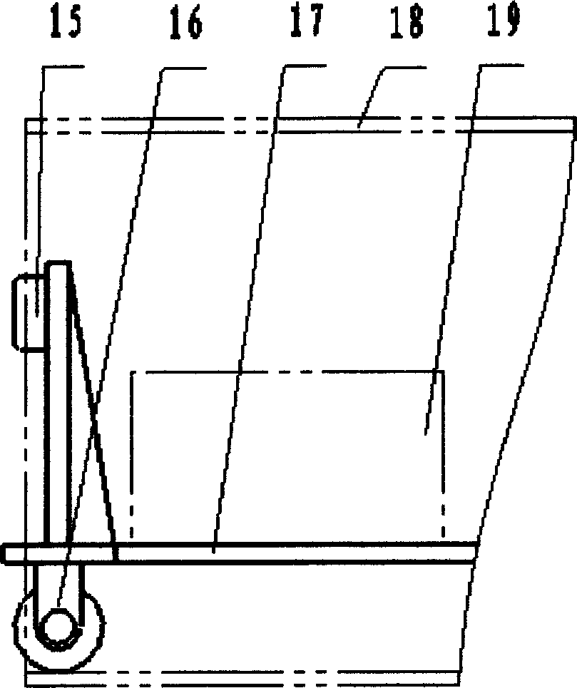
[0029] Such as figure 1 As shown, the trolley of the operation box is hinged to the mounting plate of the positioning motor, the box is installed on the trolley, and the control cables of the operation box are respectively connected to the traveling motor, positioning motor, electromagnet, and welding controller along the trolley.

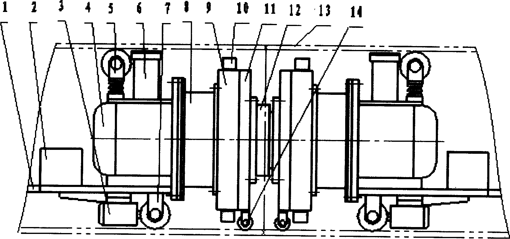
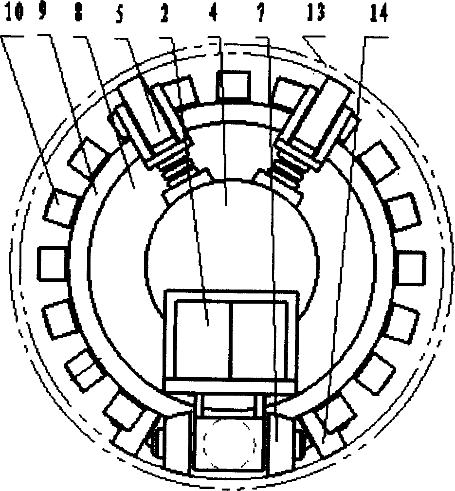
[0030] It can be seen from the figure that the steel pipe welding machine consists of a reduction gear set, a turntable, a gear mounting plate, an electromagnetic clutch, a positioning block, a connecting plate, a positioning block guide tube, a positioning plate, a tapered positioning plate, a spline shaft, a rolling bearing, a connecting short sleeve, and a positioning plate. Motor composition. The traveling mechanism is composed of a guide wheel, a pressing wheel, a traveling wheel, a traveling motor, a traveling reducer and an electromagnetic brake. The guide wheel is installed at the front end of the positioner, the pressing wheel is installe...

Embodiment 2

[0085] The basic structure of the steel pipe welding machine is exactly the same as that of the first embodiment, except that the positioning motor and the travel motor are replaced by the positioning hydraulic motor and the travel hydraulic motor, and the connection mode between the positioning hydraulic motor, the travel hydraulic motor and the reduction gear set remains unchanged: brake The electromagnet is replaced by the brake hydraulic cylinder, and the connection mode between the head end of the piston rod of the brake hydraulic cylinder and the brake shoe remains unchanged; the main contact of the contactor controlling the positioning motor, the travel motor, and the electromagnet is respectively connected to the three-position four-way electromagnetic On the electromagnet coil of the reversing valve, the positioning hydraulic motor, the traveling hydraulic motor and the brake hydraulic cylinder are controlled. The screw mechanism connecting two steel pipe welding machi...


PUM


Abstract

The invention relates to an induction soldering method and its welding equipment in welding equipment welding. Welding equipment consists of pipe-welding machine and induction heater. The equipment can automatically weld pipe transforming liquid, raw petroleum, natural gas and medium in chemical industry, and has high use value in water resources and electric power department and petrochemical industry.

Description

technical field [0001] The invention relates to a solid-phase welding method and welding equipment, more precisely, to an induction heating welding method and welding equipment for butt welding of steel pipes. The welding method and welding equipment are used in water conservancy, electric power and petrochemical enterprises to automatically weld pipelines for transporting liquid, crude oil, natural gas and chemical media. technical background [0002] At present, the pipeline systems of water conservancy, electric power and petrochemical enterprises are developing in the direction of large diameter (greater than 1000mm) and thick wall (greater than 21mm). When the pipeline is installed and welded, since the steel pipe in the installation cannot be rotated, the welding of the butt weld of the steel pipe is fixed by the steel pipe, and the welding torch is welded by rotating around the outer circumference of the steel pipe. This welding method h...

Claims


Application Information

Patent Timeline
IPC IPC(8): B23K13/01B23K13/02
Inventor 陈炯
Owner 陈炯
Why Eureka
Try Eureka