Large power continuous wave DCN laser

A laser and high-power technology, applied in the direction of lasers, laser components, laser components, etc., can solve problems such as large gaps

Inactive Publication Date: 2007-01-03
INST OF PLASMA PHYSICS CHINESE ACAD OF SCI
View PDF0 Cites 8 Cited by
  • Summary
  • Abstract
  • Description
  • Claims
  • Application Information

AI Technical Summary

Problems solved by technology

The light sources of these interferometers are all electrically excited waveguide HCN lasers w

Method used


Image

  • Large power continuous wave DCN laser

Examples


Embodiment Construction

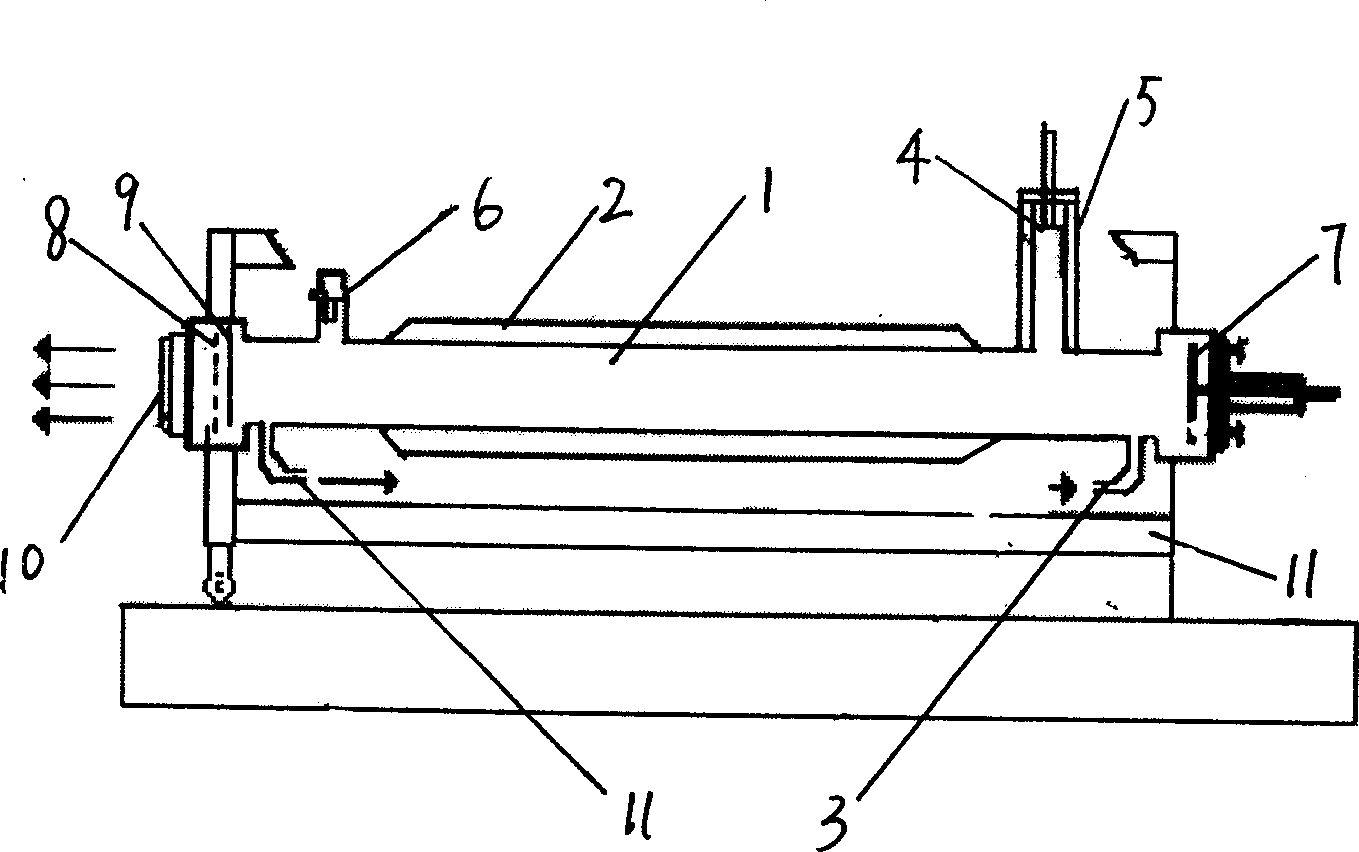
[0021] This is a high-power waveguide far-infrared DCN laser with continuous glow discharge excited by direct current. It consists of the following parts: ① discharge tube 1: the material is 17 # Glass, inner diameter 48mm, outer diameter 54mm, length 3.4m, discharge length 3m. The discharge tube 1 is equipped with an oil cooling jacket 2, and the inside of the jacket is filled with 201 # Methyl silicone oil, the oil temperature is controlled by a super thermostat. ② Electrode: The cathode 4 and the anode 6 of glow discharge are made of brass or other materials, lined with rare metals or their compounds with low sputtering rate, and a water circulation cooling jacket 5 is considered to be installed outside the cathode 4 . In order to prolong the service life of the discharge vessel 1, the cathode 4 is connected to the discharge vessel 1 via a transitional glass tube. ③Power supply: a 20KVA high voltage constant current source, the output current can be continuously adjusted...


PUM

PropertyMeasurementUnit
Diameteraaaaaaaaaa

Abstract

The present invention discloses high power continuous wave DCN laser. It contains discharge tube, anode, cathode, vacuum-pumping interface and inspiration interface on discharge tube, oil cooling jacket, waveguide type resonant cavity adopting plane cavity shape, plane reflection mirror, metallic nickel silk screen having tungsten filament, adopting x quartz plate sealing for anode end discharge tube laser output window, working medium being deuterate methane, nitrogen gas and deuterium gas or helium gas mixed gas. Said invention can continue steady operate for 168 hr. under lambda=194.7 micrometer output power about 150 mw condition, providing reliable plasma electron density measurement.

Description

technical field [0001] The invention belongs to an electrically excited far-infrared laser, more specifically a high-power continuous wave DCN laser. Background technique [0002] Electron density is one of the important parameters of fusion plasma. With the deepening of high-temperature plasma physics and diagnostic research, the further development of far-infrared laser diagnosis and related technologies, in the diagnosis of tokamak or some other fusion devices, far-infrared laser interferometer is used to measure the space-time of plasma electron density Distribution has become a routine and indispensable important means. Now, the discharge parameters of the HT-7 superconducting tokamak device have been greatly improved, and the National Science Project EAST superconducting tokamak is about to be built, which requires more reliable measurement of plasma electron density. The existing DCN glow discharge excited HCN laser can no longer meet the requirements, and a DCN glo...

Claims


Application Information

Patent Timeline
IPC IPC(8): H01S3/041H01S3/03H01S3/08H01S3/038H01S3/22
Inventor 高翔童兴德揭银先程永飞刘海庆徐强
Owner INST OF PLASMA PHYSICS CHINESE ACAD OF SCI
Why Eureka
Try Eureka