Layered manufacturing method of metal parts
A technology of layered manufacturing of metal parts, applied in the field of layered manufacturing and layered manufacturing of metal parts, can solve the problems of easy cracking, reduced processing accuracy of parts, high thermal conductivity, etc., to ensure the working environment and reduce the difficulty of manufacturing , the effect of reducing environmental pollution
- Summary
- Abstract
- Description
- Claims
- Application Information
AI Technical Summary
Problems solved by technology
Method used
Image

Examples
Embodiment 1
[0024] Embodiment one: utilize the present invention to manufacture a 10 * 10 * 10cm copper cube parts.
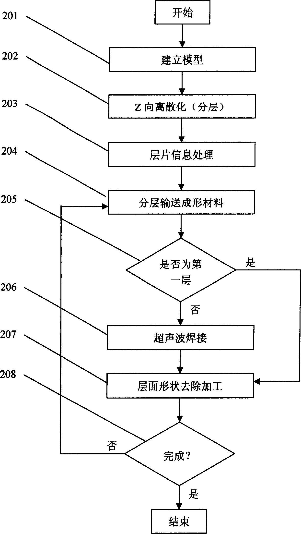
[0025] Step 201: using a computer to establish a cube model of 10×10×10 cm;
[0026] Step 202: discretize the model established in the above steps in the Z direction, that is, divide the cube model into layered models with a thickness of 1 mm, a total of 100 layers, and each layer has a square shape of 10×10 cm;
[0027] Step 203: Perform information processing on the layers divided in step 202 to obtain the boundary coordinates of each layer of the model, and use these boundary coordinates to form a curve to be processed on each layer. In this embodiment, the processing curve is a square of 10×10 cm;
[0028] Step 204: move the workbench down by 1mm, and transport the prepared copper sheet with a thickness of 1mm to the workbench from the horizontal direction;
[0029] Step 205: judge whether the layer is the first layer, if yes, go to step 207 directly, otherwise go to ...
Embodiment 2
[0033] Embodiment 2: Utilize the present invention to manufacture an aluminum spherical part with a diameter of 10 cm.
[0034] Step 201: using a computer to establish a sphere model with a diameter of 10 cm;
[0035] Step 202: discretize the sphere model established in the above steps in the Z direction, that is, divide the sphere model into layered models with a thickness of 1mm, a total of 100 layers, and each layer is in the shape of a circle with a diameter of d(i)m, where i is layer number;
[0036] Step 203: Perform information processing on the layers divided in step 202 to obtain the boundary coordinates of each layer model, and use these boundary coordinates to form the curve to be processed on each layer. In this embodiment, the processing curve of the i-th layer is the diameter d (i) circular in mm, where:
[0037] d(i)=2[50 2 -(50-i) 2 ] 1 / 2 mm, (1≤i≤50)
[0038] d(i)=2[50 2 -(i-50) 2 ] 1 / 2 mm, (50≤i≤100);
[0039] Step 204: move the workbench down by 1m...
Embodiment 3
[0044] Embodiment 3: Utilize the present invention to manufacture a 10×10×10 cm aluminum cube part.
[0045] Step 201: using a computer to establish a cube model of 10×10×10 cm;
[0046]Step 202: discretize the model established in the above steps in the Z direction, that is, divide the cube model into layered models with a thickness of 0.1 mm, a total of 100 layers, and each layer has a square shape of 10×10 cm;
[0047] Step 203: Perform information processing on the layers divided in step 202 to obtain the boundary coordinates of each layer of the model, and use these boundary coordinates to form a curve to be processed on each layer. In this embodiment, the processing curve is a square of 10×10 cm;
[0048] Step 204: moving the workbench downward by 0.1 mm, and transporting the prepared aluminum sheet with a thickness of 0.1 mm onto the workbench from the horizontal direction;
[0049] Step 205: judge whether the layer is the first layer, if yes, go to step 207 directly, ...
PUM
| Property | Measurement | Unit |
|---|---|---|
| Thickness | aaaaa | aaaaa |
| Diameter | aaaaa | aaaaa |
| Thickness | aaaaa | aaaaa |
Abstract
Description
Claims
Application Information
 - R&D
- Intellectual Property
- Life Sciences
- Materials
- Tech Scout
- Unparalleled Data Quality
- Higher Quality Content
- 60% Fewer Hallucinations
Browse by: Latest US Patents, China's latest patents, Technical Efficacy Thesaurus, Application Domain, Technology Topic, Popular Technical Reports.
© 2025 PatSnap. All rights reserved.Legal|Privacy policy|Modern Slavery Act Transparency Statement|Sitemap|About US| Contact US: help@patsnap.com