

Solar cell assembly manufacturing process
A technology of solar cells and solar cells, which is applied in the field of solar photovoltaics, can solve problems such as high welding damage rate and unsatisfactory module output power, and achieve the effect of improving welding quality, reducing the possibility of hidden cracks, and achieving obvious effects
- Summary
- Abstract
- Description
- Claims
- Application Information
AI Technical Summary
Problems solved by technology
Method used
Image

Examples
Embodiment 1
[0057] A process for manufacturing a solar cell module, comprising the steps of:
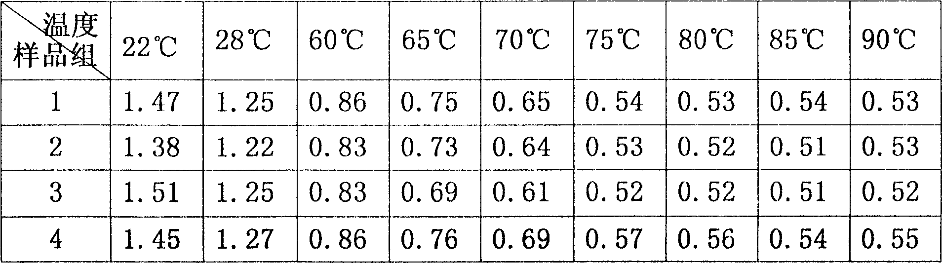
[0058] 1. Place the prepared product on a workbench with a surface temperature of 60°C,
[0059] After 2.3 minutes, use an electric soldering iron with a soldering iron tip temperature of 360°C to solder the solar cells together with interconnecting strips.
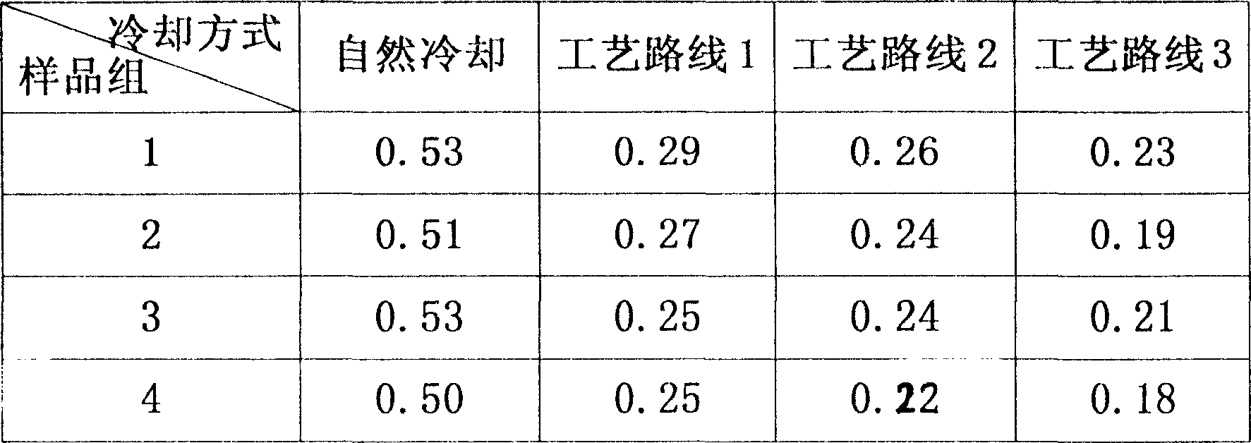
[0060]3. Naturally cool the welded crystalline silicon solar cell array to room temperature, and proceed to the next procedure.
[0061] 4. From bottom to top, glass, ethylene-vinyl acetate material, crystalline silicon solar cell array, ethylene-vinyl acetate material (EVA), and composite fluoroplastic film (TPT) are stacked together and put into Inside the vacuum laminator,
[0062] 5. Use the vacuum lamination method to evacuate the lower chamber of the laminator, pressurize and heat, press the glass / EVA / solar battery string / EVA / TPT together, take it out after forming,
[0063] 6. Add a frame to make a solar cell module.
Embodiment 2
[0065] A process for manufacturing a solar cell module, comprising the steps of:
[0066] 1. Place the prepared product on a workbench with a surface temperature of 60°C,
[0067] After 2.3 minutes, use an electric soldering iron with a soldering iron tip temperature of 360°C to solder the solar cells together with interconnecting strips.
[0068] 3. Put the welded crystalline silicon solar cell array into a 150°C heating table until the crystalline silicon solar cell array cools to the temperature of the workbench, then put it into a 100°C heating table and wait for the crystalline silicon solar cell array to cool to the workbench temperature, and then put it on Put it into a 60°C heating platform to cool, and finally cool to room temperature, and carry out the next process operation.
[0069] 4. From bottom to top, glass, ethylene-vinyl acetate material, crystalline silicon solar cell array, ethylene-vinyl acetate material (EVA), and composite fluoroplastic film (TPT) are s...
Embodiment 3
[0073] A process for manufacturing a solar cell module, comprising the steps of:
[0074] 1. Place the prepared product on a workbench with a surface temperature of 75°C,
[0075] After 2.3 minutes, use an electric soldering iron with a soldering iron tip temperature of 350°C to solder the solar cells together with interconnecting strips.
[0076] 3. After welding, put it into a 190°C heating table to cool to the workbench temperature, then put it into a 140°C heating table to cool to the workbench temperature, then put it into a 90°C heating table to cool, then put it into a 50°C heating table to cool, and finally cool it to normal temperature, proceed to the next process operation,
[0077] 4. From bottom to top, glass, ethylene-vinyl acetate material, crystalline silicon solar cell array, ethylene-vinyl acetate material (EVA), and composite fluoroplastic film (TPT) are stacked together and put into Inside the vacuum laminator,
[0078] 5. Use the vacuum lamination method...
PUM
 Abstract
Description
Claims
Application Information