
Two stage Fischer-Tropsch synthesis method

A technology of Fischer-Tropsch synthesis and synthesis gas, which is applied in the recovery of liquid hydrocarbon mixtures and the petroleum industry. It can solve the problems of low CO utilization rate and high methane production rate, and achieve the goal of improving conversion rate, high oil yield and improving activity. Effect

Active Publication Date: 2007-04-18
CHNA ENERGY INVESTMENT CORP LTD +1
View PDF1 Cites 30 Cited by
  • Summary
  • Abstract
  • Description
  • Claims
  • Application Information

AI Technical Summary

Problems solved by technology

[0005] The purpose of the present invention is to provide a two-stage Fischer-Tropsch synthesis method, which overcomes the shortcomings of high methane yield and low CO utilization when syngas is used as a raw material to produce liquid products through conventional Fischer-Tropsch synthesis methods, and simultaneously improves the efficiency of the catalyst. space-time yield

Method used


Image

  • Two stage Fischer-Tropsch synthesis method

Examples


Embodiment 1

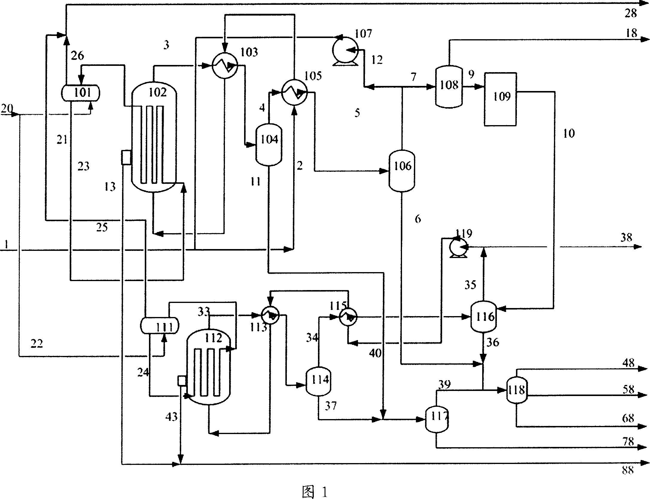
[0032] This embodiment adopts the technological process shown in Fig. 1, and the fresh feed gas is the H obtained through purification and water-gas shift after coal gasification. 2 The specific composition of syngas with a volume ratio of 1.6 to CO is shown in Table 1.

[0033] Element

[0034] Both stages of this embodiment adopt iron-based catalysts, and the weight composition of the catalysts is 100Fe: 5Cu: 5K 2 O: 25SiO 2 . The preparation method is to mix the ferric nitrate and copper nitrate solutions in proportion to form a mixed solution, and then add NaCO after heating to boiling. 3 The solution was precipitated, then filtered and washed free of alkali; the filter cake was beaten, and a quantitative amount of K 2 SiO 3 , and join the HNO 3 Wash off excess potassium ions, wash and filter, beat the filter cake and spray dry to obtain catalyst particles with a particle size range of 60-90 microns, which can be used as qualified iron-based catalysts after...

Embodiment 2

[0039] The present embodiment adopts the process flow shown in Figure 1, but removes CO removal 2 device 108 . The fresh raw gas is H2 obtained after gasification of natural gas and purification 2 The specific composition of syngas with a volume ratio of 2 to CO is shown in Table 3.

[0040] Element

[0041] Both stages of this embodiment adopt cobalt-based catalysts, and the weight composition of the cobalt catalysts is 15Co: 5Zr: 100Al 2 o 3 . The preparation method is to first pour zirconium nitrate aqueous solution into the alumina that has been roasted at 500 °C in the air in advance according to the method of incipient wetness, then use a drum to evaporate, dehydrate and dry, and then add Co(NO 3 ) 2 6H 2 O aqueous solution, after drying, impregnate the aqueous solution of cobalt nitrate again, repeat the above three times in total, until the cobalt content in the catalyst precursor meets the requirements, add a certain amount of binder, form, dry, roast...


PUM

PropertyMeasurementUnit
particle sizeaaaaaaaaaa

Abstract

This invention relates to a synthesis method of fischer-tropsch. Its preparation includes (a) Synthesis gas material enters into the first fischer-tropsch synthesis reactor to conduct fischer-tropsch synthesis reaction under the action of accelerant, (b) Segregating the first grade reaction product and letting parts of end gas return to the first fischer-tropsch reactor for recycling, and then letting C1-C4 alkanes containing in other surplus end gas to transform into synthetic gas.(c) Mixing the end gas transformed at step (b) and the second fischer-tropsch synthesis reaction circulation gas, and then entering the second fischer-tropsch synthesis reactor to conduct fischer-tropsch synthesis reaction under accelerant. (d) Segregating the second fischer-tropsch synthesis reaction product, and most of the gas returning to the second fischer-tropsch synthesis reactor for circulating reaction, and then evacuating other end gas. The transformation efficiency of CO+H2 is higher than 96% and the yield of methyl hydride is lower than 3%, and the yield of unit space-time of accelerant reaches 185 g / kg*h.

Description

technical field [0001] The invention relates to a Fischer-Tropsch synthesis method for producing hydrocarbons by using synthesis gas as a raw material, in particular to a two-stage Fischer-Tropsch synthesis method. Background technique [0002] With the continuous rise of oil prices in recent years, people pay more and more attention to the development of technologies to produce alternative oil products. Syngas is produced through coal, natural gas or other substances, and then according to the requirements of the Fischer-Tropsch synthesis catalyst for synthesis gas, through water-gas shift and synthesis The gas purification process processes the syngas, and uses the treated syngas as a raw material to produce hydrocarbons through Fischer-Tropsch synthesis, and at the same time produces oxygenated compounds, which are then processed by mature petroleum processing technology to produce high-quality, environmentally friendly oil. products, the core of which is Fischer-Tropsch ...

Claims


Application Information

Patent Timeline
Patent Type & Authority Applications(China)
IPC IPC(8): C10G5/00
Inventor 门卓武任相坤石玉林林泉王鹏袁明
Owner CHNA ENERGY INVESTMENT CORP LTD
Learn More