

Method for producing molded filter body
Patent Information
- Authority / Receiving Office
- US · United States
- Patent Type
- Patents(United States)
- Current Assignee / Owner
- SHINSHU UNIVERSITY
- Publication Date
- 2019-11-05
Smart Images
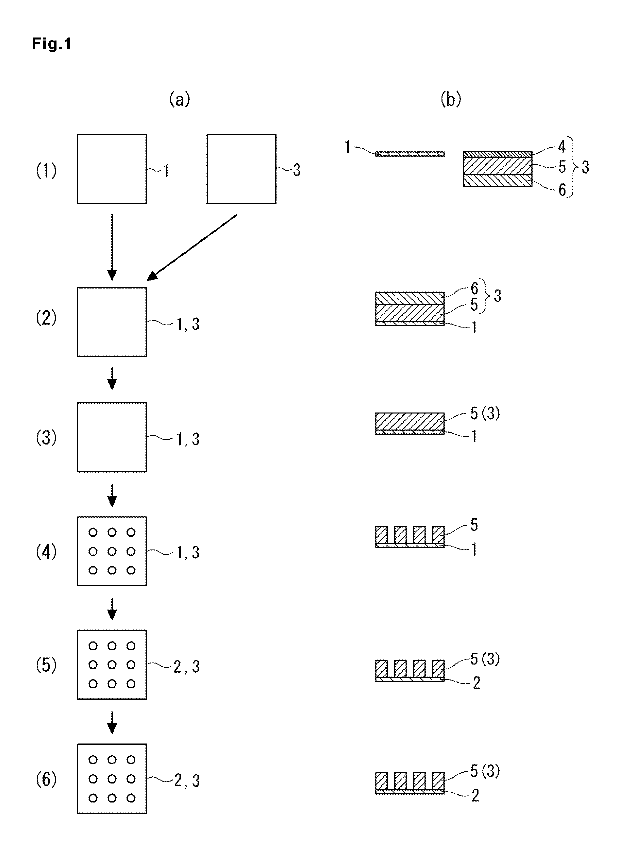
Figure 1 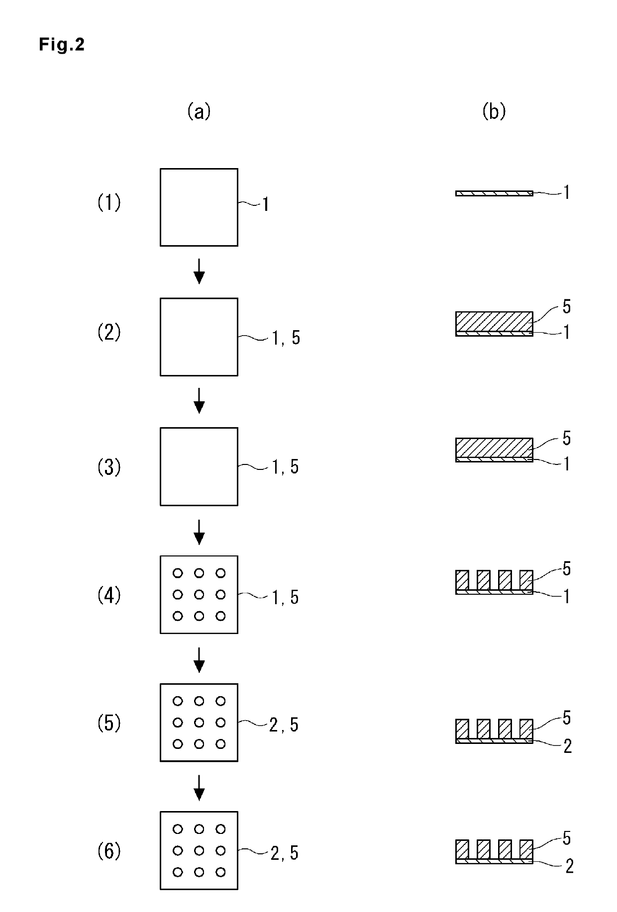
Figure 2 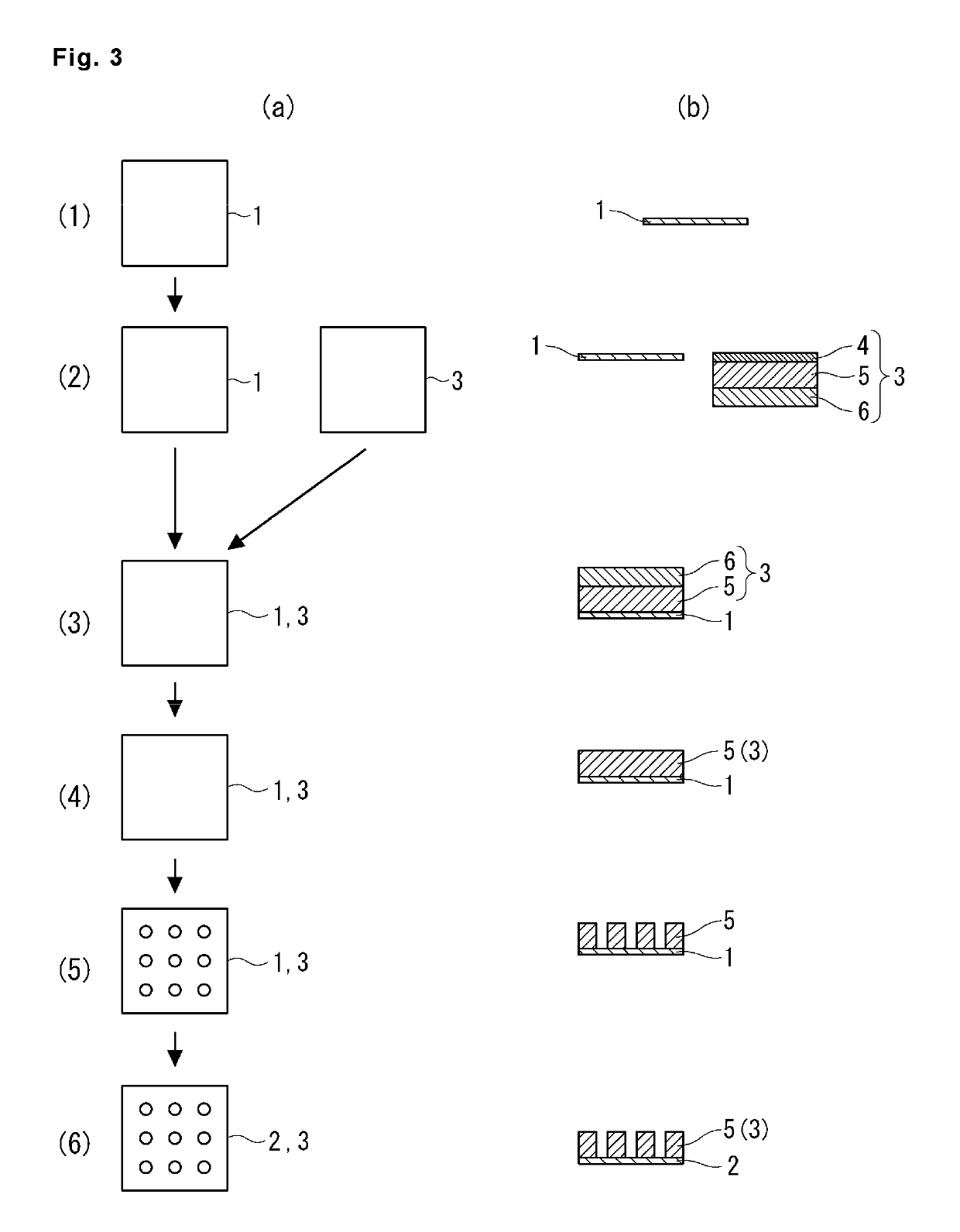
Figure 3
Abstract
Description
[0001] This application is a U.S. national phase application of co-pending international patent application number PCT / JP2015 / 082511, filed Nov. 19, 2015, which claims priority to Japanese patent application number 2014-245907, filed Dec. 4, 2014, the entire disclosures of which are hereby incorporated herein by reference.TECHNICAL FIELD
[0002] The present invention relates to a method for producing a molded filter body, and particularly relates to a method for producing a molded filter body having a filter using graphene.BACKGROUND ART
[0003] In recent years, as a filter for removing fine particles such as ions from water, other solutions, or gas, a molded filter body employing graphene in which fine water passage holes are formed has been used (Patent Literature 1).
[0004] In general, graphene is formed on a surface of copper foil or the like by a chemical vapor deposition (CVD) method (Patent Literature 2). Therefore, in the past, a process called transcription, in which ...