
Device and method for generating high-purity hydrogen by biomass pyrolysis-chemical looping combustion

a technology of biomass pyrolysis and combustion, which is applied in the direction of steam generation using hot heat carriers, sustainable manufacturing/processing, calcination, etc., can solve the problems of severe regional and global environmental issues, the principal emission co/sub>2 generated during the conversion process has not been effectively captured, and the process flow is greatly shortened. , the effect of low cost of hydrogen generation

Active Publication Date: 2020-03-03
HYLOOP TECH (BEIJING) CO LTD
View PDF8 Cites 0 Cited by
  • Summary
  • Abstract
  • Description
  • Claims
  • Application Information

AI Technical Summary

Benefits of technology

The present invention provides a device and method for generating high-purity hydrogen using biomass pyrolysis and chemical looping combustion. This technology solves the problem of long process flows and high costs associated with current methods. The process flow is greatly shortened, with high-purity hydrogen obtained through simple condensation and water removal of the product generated from the biomass pyrolysis gas. The use of steam as a purging gas prevents CO2 dilution and ensures high carbon capture efficiency. The bio-hydrogen generated is imparted with the characteristic of "carbon negative". The waste heat recovery unit improves system energy efficiency.

Problems solved by technology

The current fossil fuel-based energy systems, though meeting the energy needs of economic and social development, have incurred severe regional and global environmental issues.
Besides, the principal emission CO2 generated during the conversion process has not been effectively captured (IEA, 2007).
This leads to the situation where those existing fossil-based hydrogen energy systems will still exacerbate the greenhouse effect.
But in general, hydrogen generation by biological methods is mostly suitable for medium- and small-scale applications due to its relatively stringent biological growth conditions and slower reaction rates, whereas both hydrogen generation by supercritical conversion and hydrogen generation by plasma gasification necessitate high temperatures during their reactions, and this consequently lead to unacceptable energy consumptions.
But since it has a considerable length, numerous disadvantages arise, such as, increased operational complexity, higher energy consumption and a substantial increase in hydrogen generation costs.

Method used


Image

  • Device and method for generating high-purity hydrogen by biomass pyrolysis-chemical looping combustion
  • Device and method for generating high-purity hydrogen by biomass pyrolysis-chemical looping combustion

Examples


embodiment 1

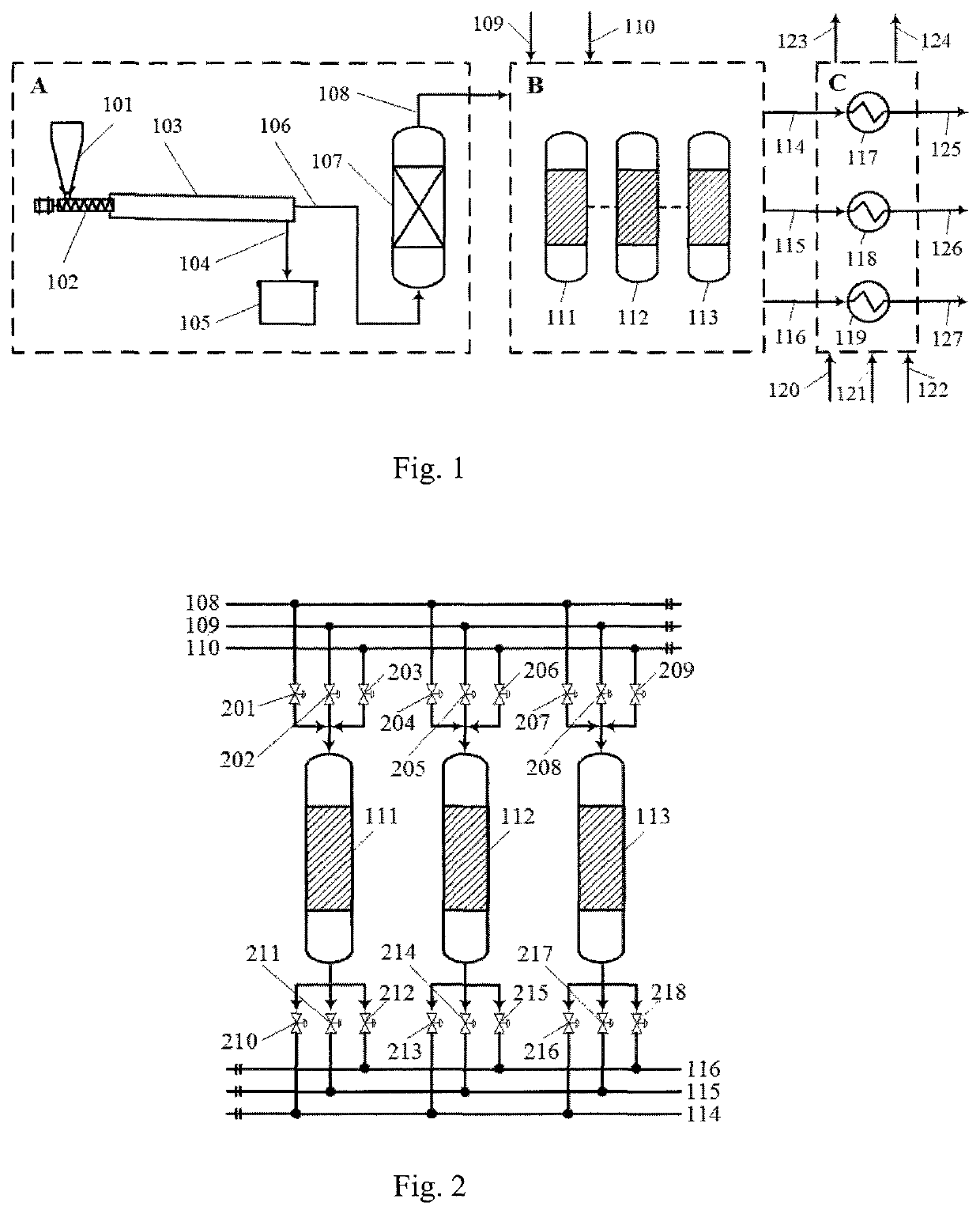
[0028]In a preferred embodiment of the present invention, as shown in FIG. 1, a device for generating high-purity hydrogen by biomass pyrolysis-chemical looping combustion comprises a biomass pyrolysis unit A, a chemical looping hydrogen generation unit B and a waste heat recovery unit C.

[0029]The biomass pyrolysis unit A comprises a vertical bin 101, a screw feeder 102, a rotary kiln pyrolysis reactor 103 and a high temperature filter 107, the vertical bin 101 conveys raw materials into the rotary kiln pyrolysis reactor 103 through the screw feeder 102, biochar generated by the rotary kiln pyrolysis reactor 103 enters into a biochar collection sump 105 via a biochar delivery pipe 104, the rotary kiln pyrolysis reactor 103 conveys the generated pyrolysis gas into a high temperature filter 107 through a pyrolysis gas delivery pipe 106, and the dust-removed pyrolysis gas enters into the chemical looping hydrogen generation unit B as a fuel via a fuel gas delivery pipe 108.

[0030]The ch...

embodiment 2

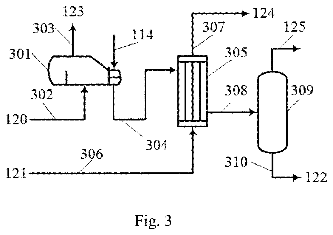
[0040]Provided in this embodiment is a method for generating high-purity hydrogen by biomass pyrolysis-chemical looping combustion. As shown in FIG. 1, FIG. 2 and FIG. 3, biomass is pyrolyzed into a pyrolysis gas at first and then the pyrolysis gas is used as a fuel for the chemical looping hydrogen generation unit to generate high-purity hydrogen, with the method being specifically as follows:

[0041]A mixture of dry sludge and furfural residue in the vertical bin 101 is pushed by the screw feeder 102 to enter the rotary kiln pyrolysis reactor 103 for pyrolysis at 600° C., with the main products being pyrolysis gases like CO, H2, etc. The resulting pyrolysis gas, after dust removal by the high temperature filter 107, enters the chemical looping hydrogen generation unit B via the fuel gas delivery pipe 108. The biochar generated by pyrolysis of the rotary kiln pyrolysis reactor 103 enters the biochar collection sump 105 via the biochar delivery pipe 104.

[0042]The clean pyrolysis gas f...


PUM

PropertyMeasurementUnit
temperatureaaaaaaaaaa
reaction temperatureaaaaaaaaaa
temperatureaaaaaaaaaa

Abstract

The present invention discloses a device and method for generating high-purity hydrogen by biomass pyrolysis-chemical looping combustion. The device comprises a biomass pyrolysis unit, a chemical looping hydrogen generation unit and a waste heat recovery unit; the biomass pyrolysis unit comprises a vertical bin, a screw feeder, a rotary kiln pyrolysis reactor and a high temperature filter; the chemical looping hydrogen generation unit comprises a path switching system of intake gas end, at least one packed bed reactor and a path switching system of tail gas end, wherein the packed bed reactor is composed of three parallel packed bed reactors I, II and III, which are continuously subjected to fuel reduction-steam oxidation-air combustion stages (steam purging stage) successively; the waste heat recovery unit comprises a waste heat boiler, a cooler and a gas-liquid separator. According to the present invention, a process flow of generating hydrogen from biomass is short, high-purity hydrogen can be obtained by simple condensation and water removal of a hydrogen-containing product that is generated after entrance of a pyrolysis gas into the chemical looping hydrogen generation unit, no complex gas purification device is employed, and the costs for hydrogen generation are low.

Description

TECHNICAL FIELD[0001]The present invention belongs to the field of hydrogen generation from biomass, and in particular relates to a device and method for generating high-purity hydrogen by biomass pyrolysis-chemical looping combustion, more particularly to generation of a pyrolysis gas by biomass pyrolysis and then generation of high-purity hydrogen by chemical looping combustion of the pyrolysis gas.BACKGROUND[0002]The current fossil fuel-based energy systems, though meeting the energy needs of economic and social development, have incurred severe regional and global environmental issues. As a clean energy, hydrogen generates only water while utilized, without causing pollutions to environments. However, approximately 96% of the current hydrogen stems from fossil energy, among which 48% comes from natural gas, 30% from tail gases of refineries and chemical plants, and 18% from coal. Besides, the principal emission CO2 generated during the conversion process has not been effectively...

Claims


Application Information

Patent Timeline
Patent Type & Authority Patents(United States)
IPC IPC(8): C01B3/24B01D3/06B01J6/00B01J8/02C10J3/00F28F17/00F22B1/18C01B3/36
CPCC10J3/005B01J6/001B01J8/0292F22B1/18C01B3/36F28F17/005B01D3/06C01B3/24Y02P20/124Y02P20/129Y02E50/14C01B3/32C10B53/02C01B2203/0205Y02E50/10Y02P20/10
Inventor WANG, WEIHUA, XIUNINGXIA, ZHOU
Owner HYLOOP TECH (BEIJING) CO LTD
Learn More