
Gasoline particulate filter

a technology of particulate filter and gasoline engine, which is applied in the direction of physical/chemical process catalyst, separation process, human health protection, etc., can solve the problems of generating particulates, particulate emissions, and treatment systems for gasoline engines that are not suitable for achieving the proposed particulate matter standard, so as to prevent the deactivation of rhodium and avoid process complexity. , the effect of high back pressur

Active Publication Date: 2020-04-21
JOHNSON MATTHEY PLC
View PDF31 Cites 9 Cited by
  • Summary
  • Abstract
  • Description
  • Claims
  • Application Information

AI Technical Summary

Benefits of technology

[0033]TWC compositions are generally provided in washcoats. Layered TWC catalysts can have different compositions for different layers. Traditionally, TWC catalysts can comprise washcoat layers having loadings of up to 2.5 g / in3 and total loadings of 5 g / in3 or more. For use with particulate traps, due to backpressure constraints, TWC catalyst washcoat layer are preferably from 1 g / in3 to 0.1 g / in3, preferably from 0.7 g / in3 to 0.25 g / in3, and most preferred from 0.6 g / in3 to 0.5 g / in3. This provides sufficient catalyst activity to oxidize carbon dioxide and hydrocarbons, as well as reduce nitrogen oxides (NOx).
[0096]At least one inventor has found that it is possible to achieve a layer thickness of the on-wall coating—or substantially on-wall coating—that varies continually along the longitudinal direction by using a higher viscosity liquid i.e. >100 cP slurry or washcoat. This arrangement has significant advantages as shown in the accompanying Examples.

Problems solved by technology

However, gasoline direct injection (GDI) engines, which are finding increasing application due to their fuel efficiency, can have lean burn conditions and stratified combustion resulting in the generation of particulates.
Particulate emissions for engines fuelled by gasoline fuel, such as gasoline direct injection engines, are being subject to regulations and existing after-treatment systems for gasoline engines are not suitable for achieving the proposed particulate matter standard.
The new Euro 6 (Euro 6 and Euro 6c) emission standard presents a number of challenging design problems for meeting gasoline emission standards.
However, it is not possible from the information provided to determine a weight ratio of OSC:alumina, except in one embodiment, wherein the TWC catalytic material is substantially free of alumina, i.e. the ratio of OSC:alumina is ∞.

Method used


Image

  • Gasoline particulate filter
  • Gasoline particulate filter
  • Gasoline particulate filter

Examples


example 2

[0118]Four wall-flow filters (4.66×4.5″ and 300 / 8 cell density) were coated with TWCs having PGM 60 / 0.57:3. Each TWC comprised a different weight ratio of Al2O3 to CeZrO4. The coated filters were calcined and aged (Hydrothermal, 1100° C. in air with 10% H2O added, 5 h).

[0119]Using a 1.41 GTDI test engine, the NOx emissions were measured based on a standard engine test. The results were as follows:

[0120]

Al2O3:CeZrO4 wt ratio1:11:21:32:1Vehicle NOx Emissions (g / km)0.0580.0460.040.054Relative NOx Emissions145.0%115.0%100.0%135.0%

[0121]As can be seen from the table, as the CeZrO4:Al2O3 wt ratio increased from 1:2 to 3:1, the relative NOx emissions decreased.

example 3

[0122]Three wall-flow filters (4.66×4.5″ and 300 / 8 cell density) were coated with TWCs having PGM 22 / 0:20:2. Each TWC comprised a different weight ratio of Al2O3 to CeZrO4. The coated filters were calcined and aged as in Example 2.

[0123]Using a 2.0l GTDI Engine Bench test engine, the NOx emissions were measured based on a standard engine test. The results were as follows:

[0124]

Al2O3:CeZrO4 wt ratio1:31:41:5NOx conversion at lambda 144.846.0544.78

[0125]To coat the wall flow filters with the TWC composition, porous substrates are immersed vertically in a portion of the catalyst slurry such that the top of the substrate is located just above the surface of the slurry. In this manner slurry contacts the inlet face of each honeycomb wall, but is prevented from contacting the outlet face of each wall. The sample is left in the slurry for about 30 seconds. The filter is removed from the slurry, and excess slurry is removed from the wall flow filter first by allowing it to drain from the ch...

example 4

ustion Tests

[0127]Two ceria-zirconia mixed oxides each doped with rare earth elements and having the composition shown in the Table below were tested for their soot combustion activity using a CATLAB-PCS combined microreactor and mass spectrometer laboratory apparatus (Hiden Analytical). A cordierite sample was tested as a control. The ceria-zirconia mixed oxides and the cordierite control were pre-fired at 500° C. for 2 hours.

[0128]Soot was collected from the engine of a European common rail light-duty diesel 2.2 litre capacity engine, which was certified to meet Euro IV emission standards. The exhaust system included a commercially available soot filter comprising an aluminium titanate wallflow filter. Soot was collected on the filter and the soot was removed from the filter by directing compressed air from a gun through the outlet channels of the filter.

[0129]To prepare the samples, 85 mg of each sample or cordierite was mixed with 15 mg of the soot using a pestle and mortar unti...


PUM

PropertyMeasurementUnit
thicknessaaaaaaaaaa
thicknessaaaaaaaaaa
d90 particle sizeaaaaaaaaaa

Abstract

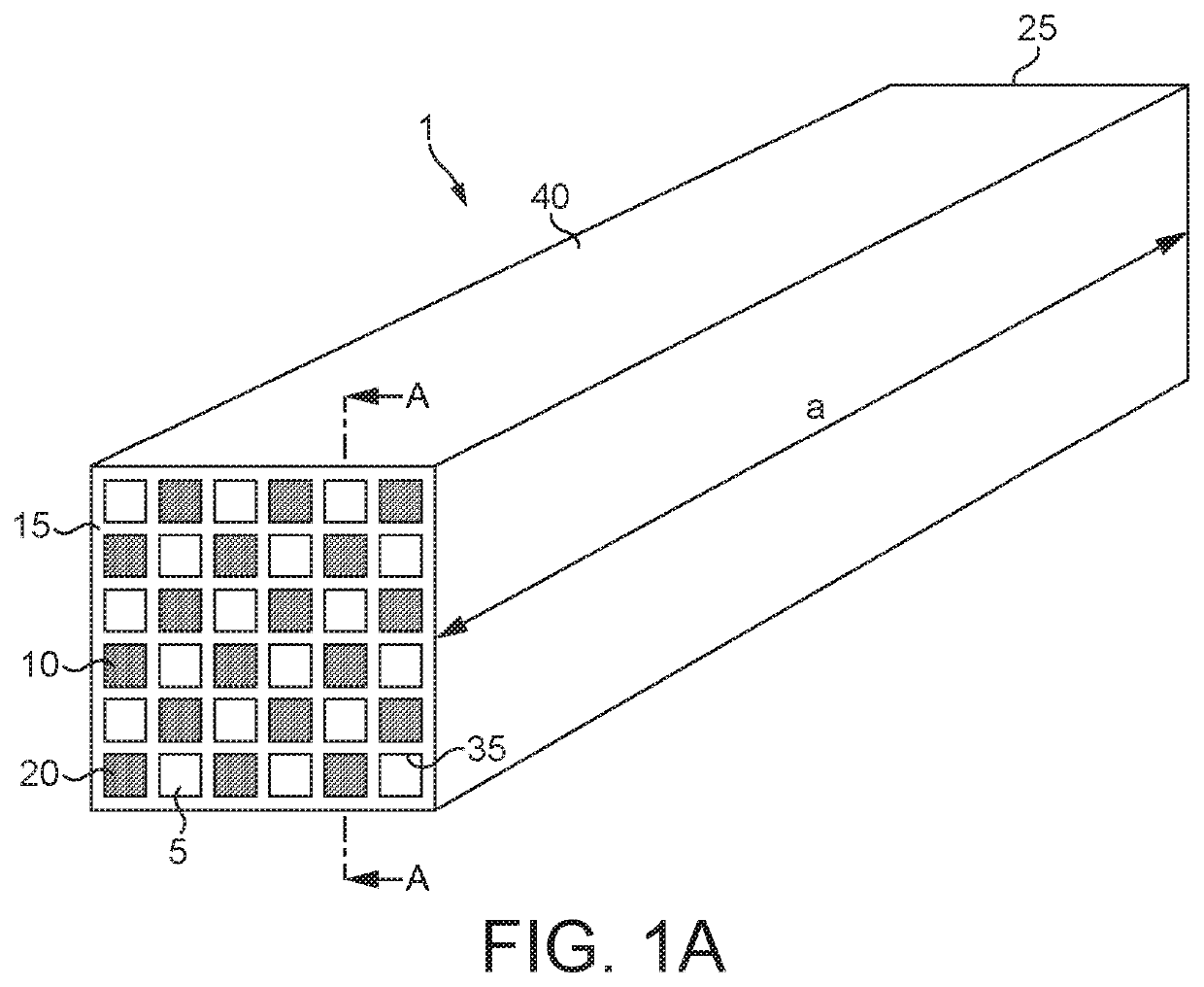
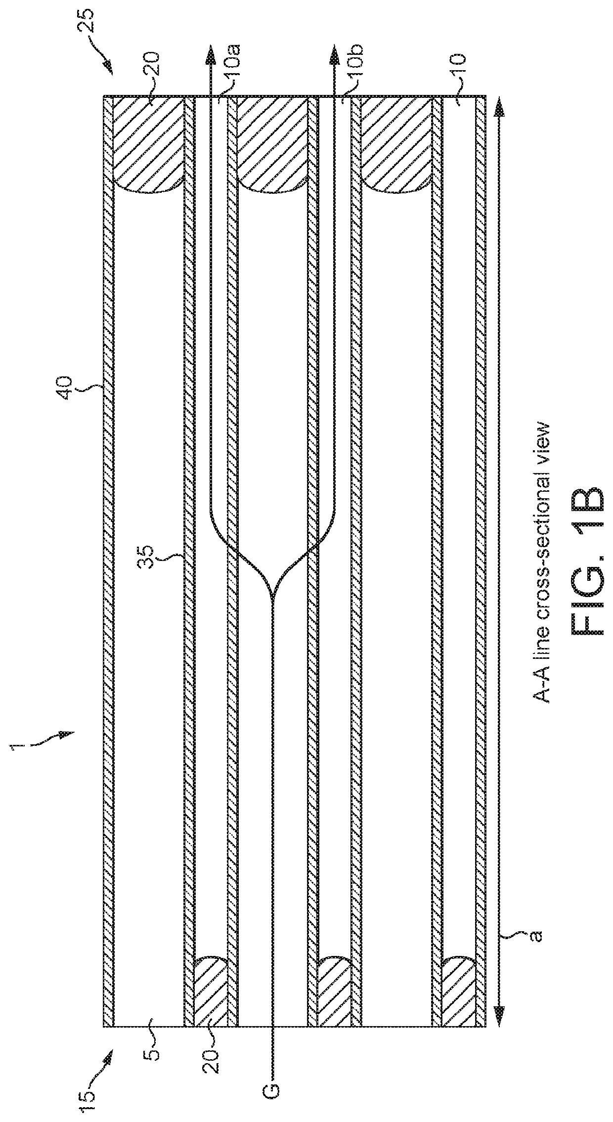
A catalytic wall-flow monolith for use in an emission treatment system comprises a porous substrate and a three-way catalyst (TWC), wherein the TWC is distributed substantially throughout the porous substrate and wherein the TWC comprises:(i) alumina;(ii) one or more platinum group metals; and(iii) an oxygen storage component (OSC),wherein the OSC comprises ceria or one or more mixed oxides comprising cerium and is present in a ratio by weight of OSC to alumina of from 65:35 to 85:15.

Description

CROSS-REFERENCE TO RELATED APPLICATIONS[0001]This national stage application claims priority benefit of PCT Patent Application No. PCTGB2016054070, filed Dec. 23, 2016 and Great Britain Patent Applications 1604915.7 and 1522917.2, filed Mar. 23, 2016 and Dec. 24, 2015, respectively, the disclosures of which are incorporated herein by reference in their entireties for all purposes.FIELD OF THE INVENTION[0002]The present invention relates to a particulate filter, in particular a catalyst-coated monolith for use in an emission treatment system of a positive ignition, e.g. spark ignition, gasoline-fuelled internal combustion engine, preferably a gasoline direct ignition engine. The monolith provides an effective method of remediating engine exhaust streams.BACKGROUND OF THE INVENTION[0003]Gasoline engines produce combustion exhaust streams containing hydrocarbons, carbon monoxide, and oxides of nitrogen in conjunction with particulates. It is known to treat the gases with a three-way ca...

Claims


Application Information

Patent Timeline
Patent Type & Authority Patents(United States)
IPC IPC(8): B01J23/46B01J37/08B01J37/02B01J35/04B01J23/10B01J21/04B01D53/94F01N13/00B01J35/00B01J23/63F01N3/28F01N3/035F01N3/10
CPCB01J21/04F01N13/00F01N3/035B01J37/0228F01N3/2803B01J23/63B01J35/0006B01J23/10B01D53/945F01N3/101B01J35/04B01J37/08B01J23/464F01N2330/06B01D2255/1021B01D2255/908B01D2255/2066B01D2255/9155F01N2510/06Y02A50/2324B01D2255/1023B01D2255/1025B01D2255/407B01D2255/2092F01N2330/02Y02T10/22Y02A50/20Y02T10/12Y02A50/2351B01D53/94B01J23/40B01J23/04B01J35/00F01N3/00B01D53/9459F01N3/20
Inventor CLOWES, LUCYDESTECROIX, OLIVERGOODWIN, JOHN BENJAMINHOWARD, MICHAEL ANTHONYLAKADAMYALI, FEZILELOCKETT, SARAH FRANCESMILLINGTON, PAULROBSON, CHRIS
Owner JOHNSON MATTHEY PLC
Learn More