Multi-electrode array for spinal cord epidural stimulation

a multi-electrode array and epidural stimulation technology, applied in the field of multi-electrode array for spinal cord epidural stimulation, can solve the problem of similar or unwanted stimulus effect in the neighborhood

Active Publication Date: 2020-09-15
RGT UNIV OF CALIFORNIA
View PDF474 Cites 8 Cited by
  • Summary
  • Abstract
  • Description
  • Claims
  • Application Information

AI Technical Summary

Benefits of technology

[0006]Improved electrode arrays for spinal cord stimulation are provided that enough mechanical flexibility and durability function over long time periods in vivo while delivering electrical stimulation to the spinal cord at relatively high voltage and / or current. The electrode arrays are flexible and can tolerate movements after implantation and provide selectable / programmable multi-site electrodes to obtain the optimal stimulation parameters.

Problems solved by technology

Dense arrays provide more stimulus pattern combinations, but similar or unwanted stimulus effect may happen in the neighborhood of the stimulated electrode due to limited stimulus spatial resolution between adjacent electrodes.

Method used


Image

  • Multi-electrode array for spinal cord epidural stimulation
  • Multi-electrode array for spinal cord epidural stimulation
  • Multi-electrode array for spinal cord epidural stimulation

Examples


example 1

Summary of Example 1

[0274]A detailed design, fabrication, characterization and test of a flexible multi-site platinum / polyimide based electrode array for electrical epidural stimulation in spinal cord prosthesis is described in this example. Carefully designed 8.4 μm-thick structure fabrication flow achieved an electrode surface modification with 3.8 times enhanced effective surface area without extra process needed. Measured impedance and phase of two type of electrodes are 2.35±0.21 KΩ and 2.10±0.11 KΩ, −34.25±8.07° and −27.71±8.27° at 1K Hz, respectively. The fabricated arrays were then in-vitro tested by a multichannel neural stimulation system in physiological saline to validate the capability for electrical stimulation. The measured channel isolation on adjacent electrode is about −34 dB. A Randles cell model was used to investigate the charging waveforms, the model parameters were then extracted by various methods. The measured charge transfer resistance, double layer capacit...

example 2

Fabrication of a Multi-Electrode Array

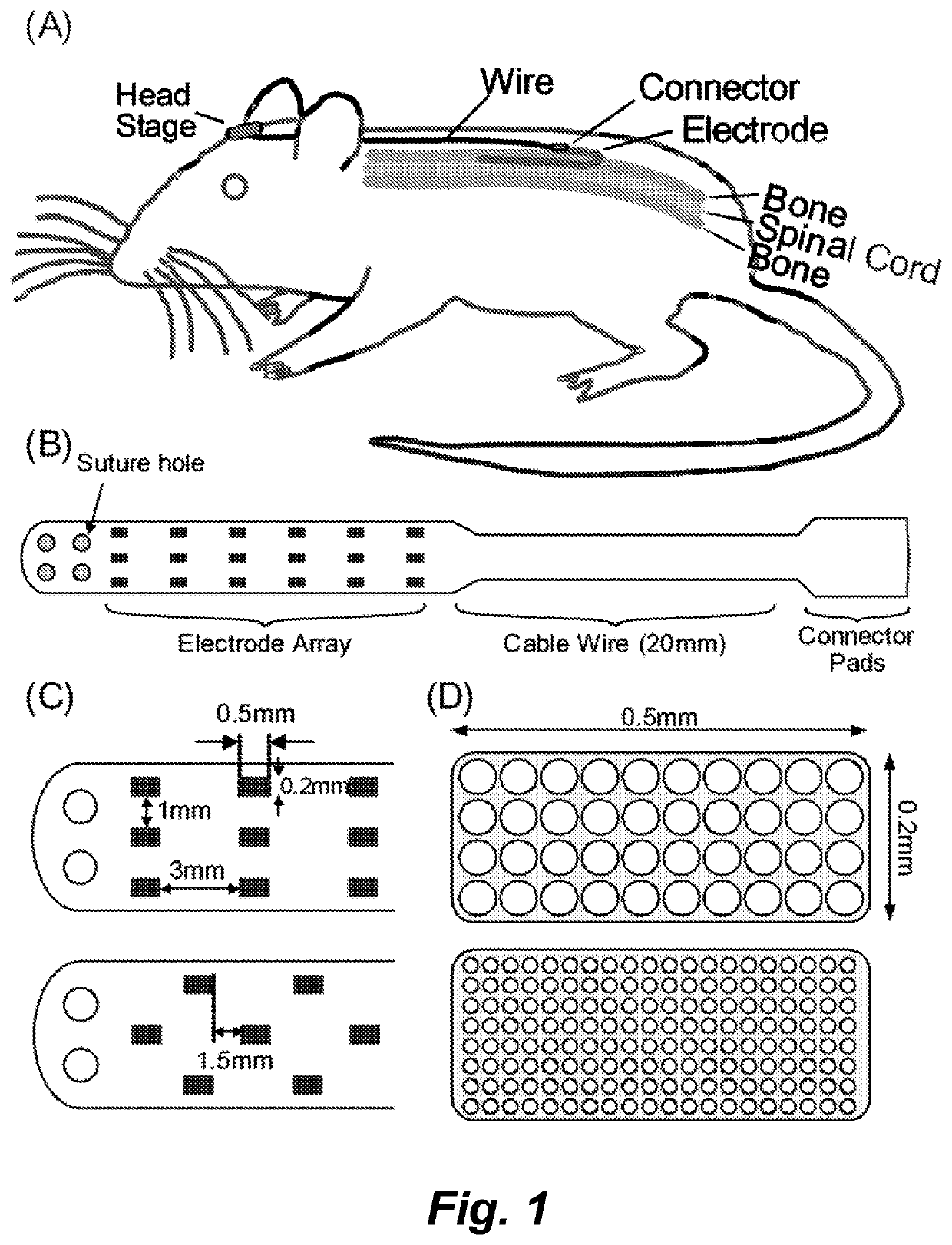
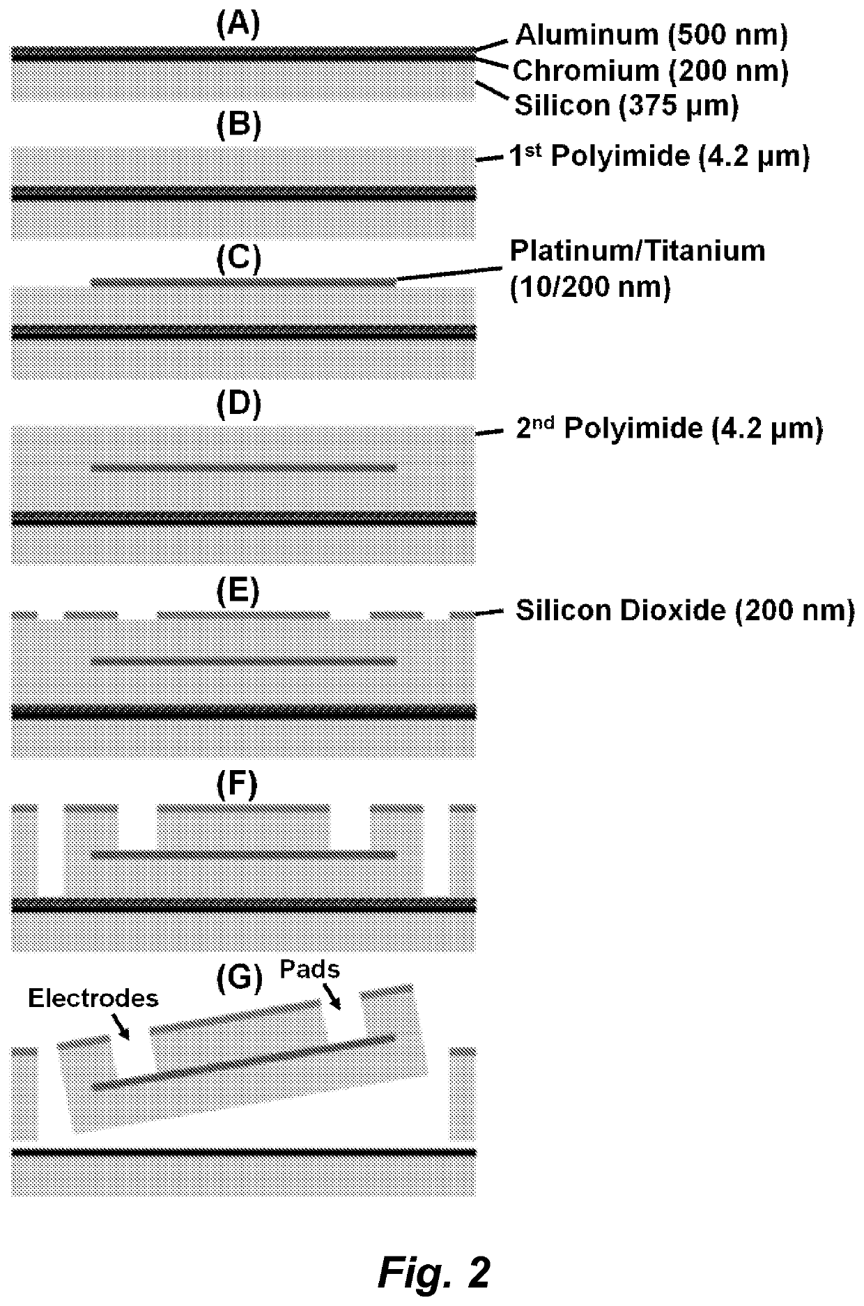
[0287]The following protocol was used to fabricate the multi-electrode array shown in FIG. 1:

[0288]A) Chromium / Aluminum (200 nm / 500 nm) layer was deposited by E-beam evaporated deposition (CHA Mark 40) on to a handle silicon wafer.

[0289]B) Adhesion promoter (VM-651, HD Microsystems) was applied onto the Chromium / Aluminum layer to create a Si—C bond and provide additional adhesion for the first polyimide layer.

[0290]C) A 4.2 μm polyimide (PI-2611, HD Microsystems) was spin-coated onto the wafer, and cured in 350° C. for 30 minutes in a nitrogen-controlled oven to form full cross-link in the polyimide.

[0291]D) Positive photoresister AZ4620 was spin-coated onto the wafer. Create the metal pattern by microphotolithography.

[0292]E) An oxygen-plasma roughening process was applied to the polyimide layer for 30 seconds to enhance the adhesion performance.

[0293]F) Titanium / Platinum (10 nm / 200 nm) layer was defined and deposited using E-beam evaporated de...


PUM


Abstract

In certain embodiments an electrode array for epidural stimulation of the spinal cord is provided where the array comprises a plurality of electrodes disposed on a flexible polymer substrate; said electrodes being electrically connected to one or more lead wires and / or connection points on an electrical connector; where the electrodes of said array are bonded to said polymer so that the electrodes can carry an electrical stimulation signal having a voltage, frequency, and current sufficient to provide epidural stimulation of a spinal cord and / or brain in vivo or in a physiological saline solution, without separation of all or a part of an electrode from the polymer substrate.

Description

CROSS-REFERENCE TO RELATED APPLICATIONS[0001]This application is a U.S. 371 National Phase of PCT / US2015 / 047268, filed Aug. 27, 2015, which claims benefit of and priority to U.S. Ser. No. 62 / 042,672, filed on Aug. 27, 2014, and to U.S. Ser. No. 62 / 171,427, filed on Jun. 5, 2015, all of which are incorporated herein by reference in their entirety for all purposes.STATEMENT OF GOVERNMENTAL SUPPORT[0002]This invention was made with Government support under EB007615 and NS062009, awarded by the National Institutes of Health. The Government has certain rights in the invention.NOTICE OF MATERIAL SUBJECT TO COPYRIGHT PROTECTION[0003]A portion of the material in this patent document is subject to copyright protection under the copyright laws of the United States and of other countries. The owner of the copyright rights has no objection to the facsimile reproduction by anyone of the patent document or the patent disclosure, as it appears in the United States Patent and Trademark Office publi...

Claims


Application Information

Patent Timeline
Patent Type & Authority Patents(United States)
IPC IPC(8): A61N1/05A61N1/04A61N1/36
CPCA61N1/36007A61N1/36071A61N1/36107A61N1/0476A61N1/0553A61N1/36067A61N1/3611A61N1/36082A61N1/0551A61N1/0558A61N1/36114
Inventor LIU, WENTAIEDGERTON, VICTOR REGGIECHANG, CHIH-WEIGAD, PARAG
Owner RGT UNIV OF CALIFORNIA
Why Eureka
Try Eureka