Fluidized bed gas distributor, reactor using fluidized bed gas distributor, and method for producing para-xylene and co-producing light olefins

a technology of distributor and distributor, which is applied in the direction of catalyst regeneration/reactivation, physical/chemical process catalyst, bulk chemical production, etc., can solve the problem of low achieve high conversion rate of toluene, improve reaction yield, and improve the effect of reaction yield

Active Publication Date: 2021-04-06
DALIAN INST OF CHEM PHYSICS CHINESE ACAD OF SCI
View PDF38 Cites 1 Cited by
  • Summary
  • Abstract
  • Description
  • Claims
  • Application Information

AI Technical Summary

Benefits of technology

[0007]According to an aspect of the present application, this is provided a fluidized bed gas distributor to achieve mass transfer control by distributing different raw materials stream in different regions in a co-feed system with a large difference in raw material reaction rates, so as to coordinate and optimize a co-feed system and improve the reaction yield. As a typical reaction system, the reaction of preparing para-xylene by the alkylation of toluene and methanol, in which the reaction rates of the alkylation reaction and the MTO reaction are greatly different, and the MTO reaction inhibits the alkylation reaction. Therefore, the conversion rate of toluene is low. The fluidized bed gas distributor provided by the present application coordinates and optimizes the competition between the alkylation reaction and the MTO reaction through mass transfer control, thereby improving the conversion rate of toluene and the yield of para-xylene.

Problems solved by technology

Therefore, the conversion rate of toluene is low.

Method used


Image

  • Fluidized bed gas distributor, reactor using fluidized bed gas distributor, and method for producing para-xylene and co-producing light olefins
  • Fluidized bed gas distributor, reactor using fluidized bed gas distributor, and method for producing para-xylene and co-producing light olefins
  • Fluidized bed gas distributor, reactor using fluidized bed gas distributor, and method for producing para-xylene and co-producing light olefins

Examples


example 1

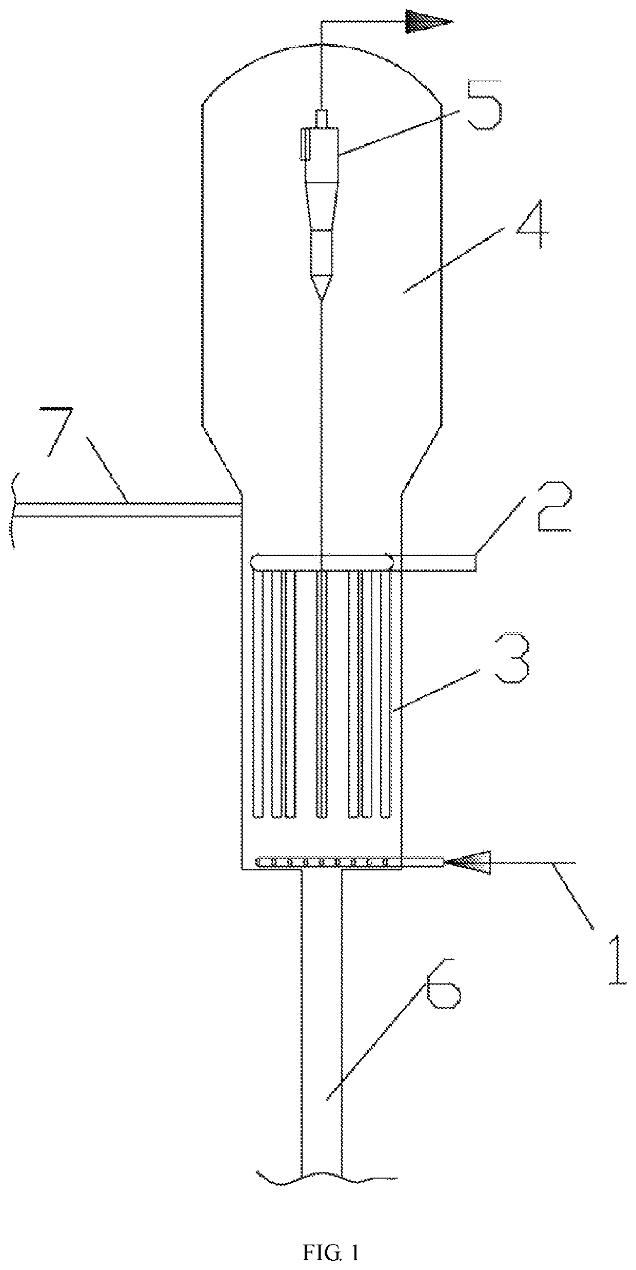
[0092]In the fluidized bed reactor as shown in FIG. 1, para-xylene and light olefins are produced. The fluidized bed reactor comprises the first gas distributor 1, the second gas distributor 2, the reaction zone 3, the settling zone 4, the gas-solid separator 5, the stripping zone 6 and the regenerated catalyst delivery pipe 7. The first gas distributor 1 is placed at the bottom of the reaction zone 3. The second gas distributor 2 is placed in the reaction zone 3. The settling zone 4 is above the reaction zone 3. The gas-solid separator 5 is disposed within the settling zone 4, and the product outlet is set on the top. The stripping zone 6 is below the reaction zone 3, and the upper portion of the reaction zone 3 is connected with the regenerated catalyst delivery pipe 7.

[0093]The first gas distributor 1 is a branched pipe distributor, and the second gas distributor 2 is a microporous gas distributor.

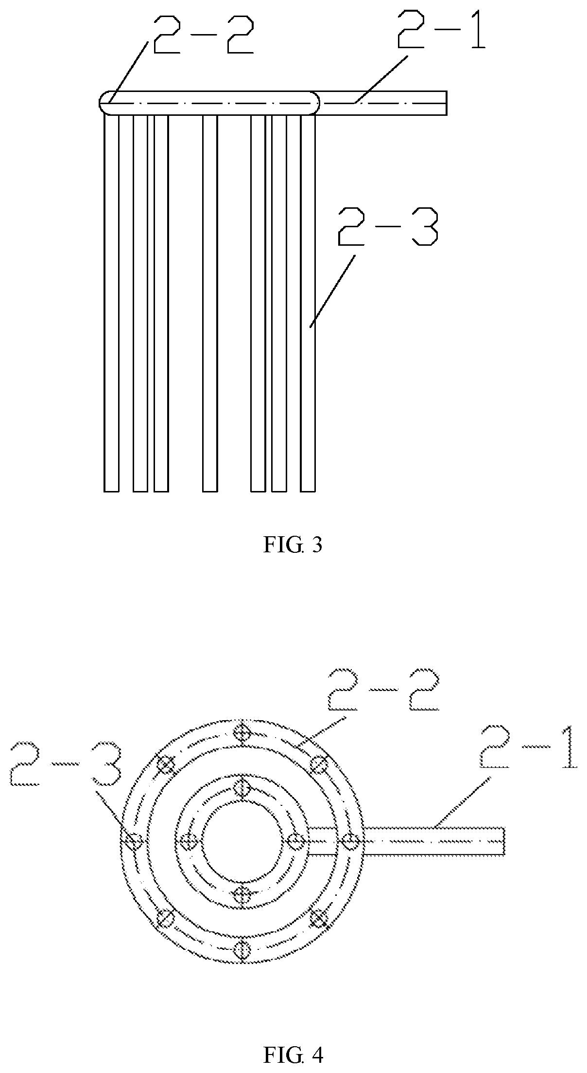
[0094]As shown in FIG. 3, the microporous gas distributor includes the intake pipe ...

example 2

[0099]In the fluidized bed reactor as shown in FIG. 1, para-xylene and light olefins are produced. The fluidized bed reactor comprises the first gas distributor 1, the second gas distributor 2, the reaction zone 3, the settling zone 4, the gas-solid separator 5, the stripping zone 6 and the regenerated catalyst delivery pipe 7. The first gas distributor 1 is placed at the bottom of the reaction zone 3. The second gas distributor 2 is placed in the reaction zone 3. The settling zone 4 is above the reaction zone 3. The gas-solid separator 5 is disposed within the settling zone 4, and the product outlet is set on the top. The stripping zone 6 is below the reaction zone 3, and the upper portion of the reaction zone 3 is connected with the regenerated catalyst delivery pipe 7.

[0100]The first gas distributor 1 is a branched pipe distributor, and the second gas distributor 2 is a microporous gas distributor.

[0101]As shown in FIG. 3, the microporous gas distributor includes the intake pipe ...

example 3

[0106]In the fluidized bed reactor as shown in FIG. 1, para-xylene and light olefins are produced. The fluidized bed reactor comprises the first gas distributor 1, the second gas distributor 2, the reaction zone 3, the settling zone 4, the gas-solid separator 5, the stripping zone 6 and the regenerated catalyst delivery pipe 7. The first gas distributor 1 is placed at the bottom of the reaction zone 3. The second gas distributor 2 is placed in the reaction zone 3. The settling zone 4 is above the reaction zone 3. The gas-solid separator 5 is disposed within the settling zone 4, and the product outlet is set on the top. The stripping zone 6 is below the reaction zone 3, and the upper portion of the reaction zone 3 is connected with the regenerated catalyst delivery pipe 7.

[0107]The first gas distributor 1 is a plate distributor with blast caps, and the second gas distributor 2 is a microporous gas distributor.

[0108]As shown in FIG. 3, the microporous gas distributor includes the inta...


PUM

PropertyMeasurementUnit
porosityaaaaaaaaaa
pore diameteraaaaaaaaaa
temperatureaaaaaaaaaa

Abstract

Disclosed are a fluidized bed gas distributor and a fluidized bed reactor, the fluidized bed reactor comprising a first distributor (1) and a second distributor (2), wherein the first distributor (1) is located at the bottom of a fluidized bed, and second distributor (2) is located downstream of a gas from the first distributor (1). Also disclosed is a method for producing a para-xylene and co-producing light olefins, the method comprising the following steps: material stream A enters a reaction zone (3) of a fluidized bed reactor from a first gas distributor (1); material stream B enters the reaction zone (3) of the fluidized bed reactor from a second gas distributor (2); and the reactants are brought into contact with a catalyst in the reaction zone (3) to generate a gas phase stream comprising para-xylene and light olefins.

Description

TECHNICAL FIELD[0001]The present invention relates to a distributor in a fluidized bed, a reactor and a production method for producing para-xylene (PX) and co-producing light olefins, and is particularly suitable for a fluidized bed reactor and a production method for preparing para-xylene and co-producing light olefins by the alkylation of toluene and methanol, which belongs to the field of chemistry and chemical industry.BACKGROUND[0002]Para-xylene (PX) is one of the basic organic raw materials in the petrochemical industry, which has a wide range of applications in chemical fiber, synthetic resins, pesticides, pharmaceuticals and polymer materials. At present, the production of para-xylene mainly uses toluene, C9 aromatics and mixed xylene as raw materials, and para-xylene is obtained by disproportionation, isomerization, adsorption separation or cryogenic separation. Since the para-xylene content in the product is controlled by thermodynamics, para-xylene only accounts for 22˜2...

Claims


Application Information

Patent Timeline
Patent Type & Authority Patents(United States)
IPC IPC(8): B01J8/18B01J8/00B01J8/26B01J29/40B01J29/90C07C1/20C07C2/86C07C9/02C07C15/08
CPCB01J8/1827B01J8/005B01J8/1872B01J8/26B01J29/40B01J29/90C07C1/20C07C2/864C07C2/865B01J2208/00017B01J2208/00548B01J2208/00893C07C9/02C07C15/08C07C2529/40C07C11/04C07C11/06C07C11/08C07C15/06B01J8/18Y02P20/52Y02P30/20Y02P30/40B01J2208/00752B01J2208/00902B01J2208/00938B01J38/06
Inventor ZHANG, TAOYE, MAOJIA, JINMINGLIU, ZHONGMINZHANG, JINLINGTANG, HAILONGHE, CHANGQINGWANG, XIANGAOZHANG, CHENGLI, HUAZHAO, YINFENGLI, CHENGGONG
Owner DALIAN INST OF CHEM PHYSICS CHINESE ACAD OF SCI
Why Eureka
Try Eureka