
Porous structure Si Cu composite electrode of lithium ion battery and preparation method thereof

a lithium ion battery and composite electrode technology, applied in the manufacture process of electrodes, cell components, electrochemical generators, etc., can solve the problems of weakening the conductivity of the anode structure, deteriorating the electrical conductivity, and difficulty in further meeting the demands of higher energy/density applications, so as to increase the reaction efficiency of lithium insertion combinations, improve the electron transmission efficiency, and increase the contact area

Active Publication Date: 2021-07-13
BEIJING UNIV OF TECH
View PDF2 Cites 0 Cited by
  • Summary
  • Abstract
  • Description
  • Claims
  • Application Information

AI Technical Summary

Benefits of technology

The present patent has the following advantages: 1) The use of a block porous copper structure as a binder and conductive agent helps to prevent the pulverization and shedding of active substance silicon particles, and improves electron transmission efficiency. 2) The porous structure increases the contact area between silicon and electrolyte, leading to an improved reaction efficiency for lithium insertion combination. This results in a high capacity and excellent cycle performance of the composite electrode under high mass loading of silicon. 3) The manufacturing method combines traditional powder metallurgy, diffusion welding, and de-alloying technologies, making it a mature and simple process.

Problems solved by technology

At present, the anode material of lithium ion batteries is mainly concentrated on graphite which has been close to the theoretical specific capacity of 372 mAh / g and is difficult to further meet the demands for higher energy / density applications.
However, Si has problems such as severe pulverization and shedding and rapid deterioration of electrical conductivity during charge-discharge processes, which become obstacles for using it as anode material.
In the phase reactions, a stress caused by inhomogeneous volumetric expansion of Si (volume change can reach 270%) eventually causes the pulverization of Si and the shedding of Si from a current collector and lose its electrical contact with the current collector, finally resulting in the weakening in the conductivity of the anode structure.
However, both of these ways will decreases a mass loading capacity of Si and thus limit the increase in total capacity and practical application.

Method used


Image

  • Porous structure Si Cu composite electrode of lithium ion battery and preparation method thereof
  • Porous structure Si Cu composite electrode of lithium ion battery and preparation method thereof

Examples


example 1

[0049]Raw materials: Si, Cu, Al powders with a weight percentage of Si:Cu:Al=10:72:18, the mesh size of Si powder is −325 mesh, the mesh size of Cu powder is −300 mesh and mesh size of Al powder is −325 mesh.

[0050]Etching solution: 3 M HCl solution.

[0051]Preparation Process:

[0052]Step 1, Compression Moulding

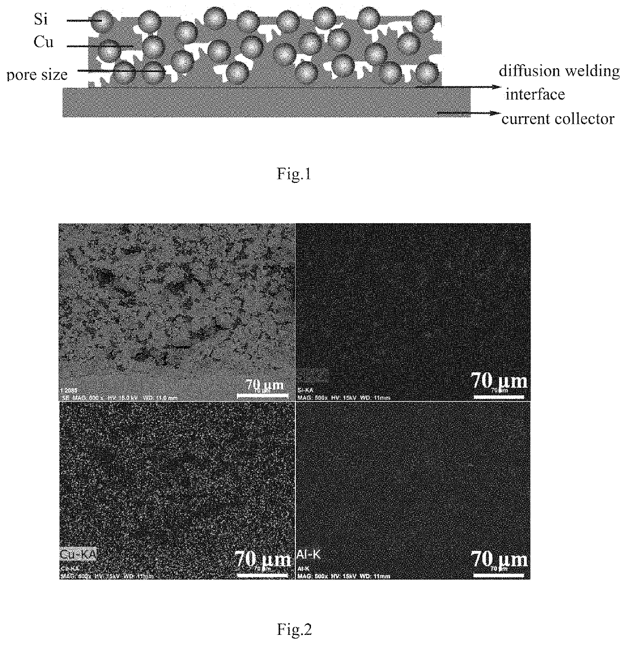
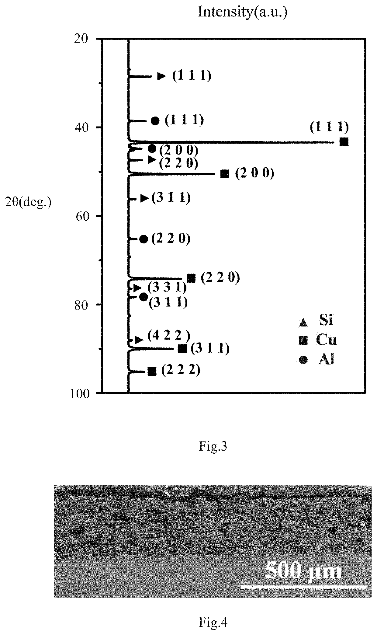
[0053]Using Shanghai Xinnuo SYP-30T type compressing machine to perform compression moulding of the mixed Si / Cu / Al powder with a pressure of 0.4 MPa for 5 minutes to obtain a compression moulded Si / Cu / Al material with a diameter of 8 mm and a thickness of about 200 μm. A SEM view and an EDS element distribution view of a cross-section of a precursor alloy of the material is shown in FIG. 2.

[0054]Step 2, Sintering and Diffusion Welding

[0055]By using the vacuum diffusion welding furnace HT-QA-25 produced by Beijing Hangtian Jinxiang Equipment Co., Ltd., the compression moulded Si / Cu / Al material is closely laminated to a Cu current collector, and then placed in the vacuum furnace an...

example 2

[0058]Raw materials: Si, Cu, Al powders with a weight percentage of Si:Cu:Al=14:72:14, the mesh size of Si powder is −325 mesh, the mesh size of Cu powder is −300 mesh and mesh size of Al powder is −325 mesh.

[0059]Etching solution: 3 M HCl solution.

[0060]Preparation Process:

[0061]Step 1, Compression Moulding

[0062]Using Shanghai Xinnuo SYP-30T type compressing machine to perform compression moulding of the mixed Si / Cu / Al powder with a pressure of 0.4 MPa for 5 minutes to obtain a compression moulded Si / Cu / Al material with a diameter of 8 mm and a thickness of about 200 μm.

[0063]Step 2, Sintering and Diffusion Welding

[0064]By using the vacuum diffusion welding furnace HT-QA-25 produced by Beijing Hangtian Jinxiang Equipment Co., Ltd., the compression moulded Si / Cu / Al material is closely laminated to a Cu current collector, and then placed in the vacuum furnace and heated to 470° C. with an applied pressure of 0.4 MPa, and the temperature and pressure is maintained for 45 minutes. The ...

example 3

[0067]Raw materials: Si, Cu, Al powders with a weight percentage of Si:Cu:Al=25:50:25, the mesh size of Si powder is −325 mesh, the mesh size of Cu powder is −300 mesh and mesh size of Al powder is −325 mesh.

[0068]Etching solution: 3M HCl solution.

[0069]Preparation Process:

[0070]Step 1, Compression Moulding

[0071]Using Shanghai Xinnuo SYP-30T type compressing machine to perform compression moulding of the mixed Si / Cu / Al powder with a pressure of 0.4 MPa for 5 minutes to obtain a compression moulded Si / Cu / Al material with a diameter of 8 mm and a thickness of about 200 μm.

[0072]Step 2, Sintering and Diffusion Welding

[0073]By using the vacuum diffusion welding furnace HT-QA-25 produced by Beijing Hangtian Jinxiang Equipment Co., Ltd., the compression moulded Si / Cu / Al material is closely laminated to the Cu current collector, and then placed in the vacuum furnace and heated to 470° C. with an applied pressure of 0.4 MPa, and the temperature and pressure is maintained for 45 minutes. The...


PUM

PropertyMeasurementUnit
temperatureaaaaaaaaaa
coulombic efficiencyaaaaaaaaaa

Abstract

The present disclosure discloses a porous structure Si / Cu composite electrode of a lithium ion battery and a preparation method thereof. The composite electrode comprises an active substance, a bulk porous Cu and a current collector, wherein the active substance Si is embedded into the bulk porous Cu, and the bulk porous Cu is in metallurgical bonding with the current collector and plays a dual role of “binder” and “conductive agent”, which not only relieves the pulverization and the shedding of the active substance Si particles but also improves electron transmission efficiency; and meanwhile, the porous structure increases the contact area between the active substance Si and electrolyte and increases the reaction efficiency of lithium insertion combination. The method of preparing the composite electrode comprises: with Si, Cu and Al powders as raw materials, preparing a Si—Cu—Al precursor alloy on the Cu current collector by powder metallurgy and diffusion welding technology; and removing Al element in the Si—Cu—Al precursor alloy by using a chemical de-alloying method to obtain a Si / Cu composite electrode with a porous-structure.

Description

CROSS-REFERENCE TO RELATED PATENT APPLICATIONS[0001]The present application is a continuation of International Application No. PCT / CN2017 / 080802, filed Apr. 17, 2017, which claims the benefit of priority to Chinese Application No. CN 201710183177.3, filed on Mar. 24, 2017, the content of which is incorporated herein by reference in its entirety.FIELD OF THE INVENTION[0002]The present disclosure relates to the structure of an anode of a lithium ion battery and a preparation method thereof, and more specially, to a Si / Cu composite electrode with a porous structure and a preparation method thereof, which belongs to the field of advanced manufacturing technology.BACKGROUND[0003]Lithium Ion Batteries (LIBs) have the advantages of high capacity, no memory effect, fast reversible charge-discharge, a high coulombic efficiency and so on and have been widely used in the fields of mobile phones, notebook computers, electric vehicles and energy storage. At present, the anode material of lithium...

Claims


Application Information

Patent Timeline
Patent Type & Authority Patents(United States)
IPC IPC(8): H01M4/76H01M4/04H01M4/134H01M4/1395H01M4/36H01M4/38H01M4/66H01M10/0525B22F1/06
CPCH01M4/762H01M4/043H01M4/049H01M4/134H01M4/1395H01M4/362H01M4/386H01M4/661H01M4/667H01M10/0525H01M4/0471H01M4/0492H01M4/62H01M4/621H01M4/626H01M4/628B22F1/06B22F5/006B22F3/1134C22C1/0425B22F2003/244C22C1/0416B22F2999/00B22F2998/10B22F2201/20Y02E60/10B22F3/11B22F3/02B22F3/10
Inventor HUANG, TINGCUI, MENGYAXIAO, RONGSHIYANG, WUXIONGWU, QIANG
Owner BEIJING UNIV OF TECH
Learn More