Method for analyzing polymer membrane
a polymer membrane and analysis method technology, applied in the field of analyzing a polymer membrane, to achieve the effect of effectively removing noise, shortening analysis time, and improving structural analysis accuracy of the polymer membran
- Summary
- Abstract
- Description
- Claims
- Application Information
AI Technical Summary
Benefits of technology
Problems solved by technology
Method used
Image
Examples
example 1
[0044]A trench substrate was prepared in the following manner. A silicon wafer was applied as a substrate. A layer of SiO was formed on the substrate to a thickness of about 200 nm or so by a known deposition method. Subsequently, a BARC (bottom anti-reflective coating) was coated on the layer of SiO to a thickness of about 60 nm or so, and a PR (photoresist, for KrF, positive-tone resist) layer was again coated thereon to a thickness of about 400 nm or so. Subsequently, the PR layer was patterned by a KrF stepper exposure method. Subsequently, using the patterned PR layer as a mask, the lower BARC layer and SiO layer were etched by an RIE (reactive ion etching) method, and the residue was removed to form a trench structure.
[0045]A random copolymer of a compound (DPM-C12) and pentafluorostyrene was coated inside the trenches and fixed on the silicon wafer through a thermal annealing process at 160° C. for 24 hours, and to remove unreacted materials, a sonication process was treated ...
example 2
[0052]A coating solution prepared by diluting a block copolymer of a compound (DPMC12) and pentafluorostyrene in toluene in a solid content concentration of 1.5 wt % was spin-coated inside the trenches manufactured by the method mentioned in Example 1, dried at room temperature for about 1 hour and then again subjected to the thermal annealing at a temperature of about 160 to 250° C. for about 1 hour to form a self-assembled membrane.
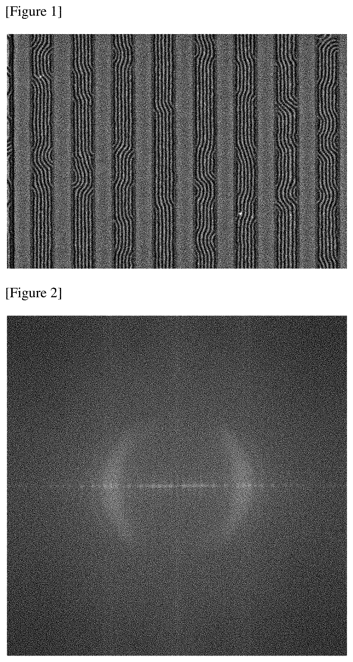
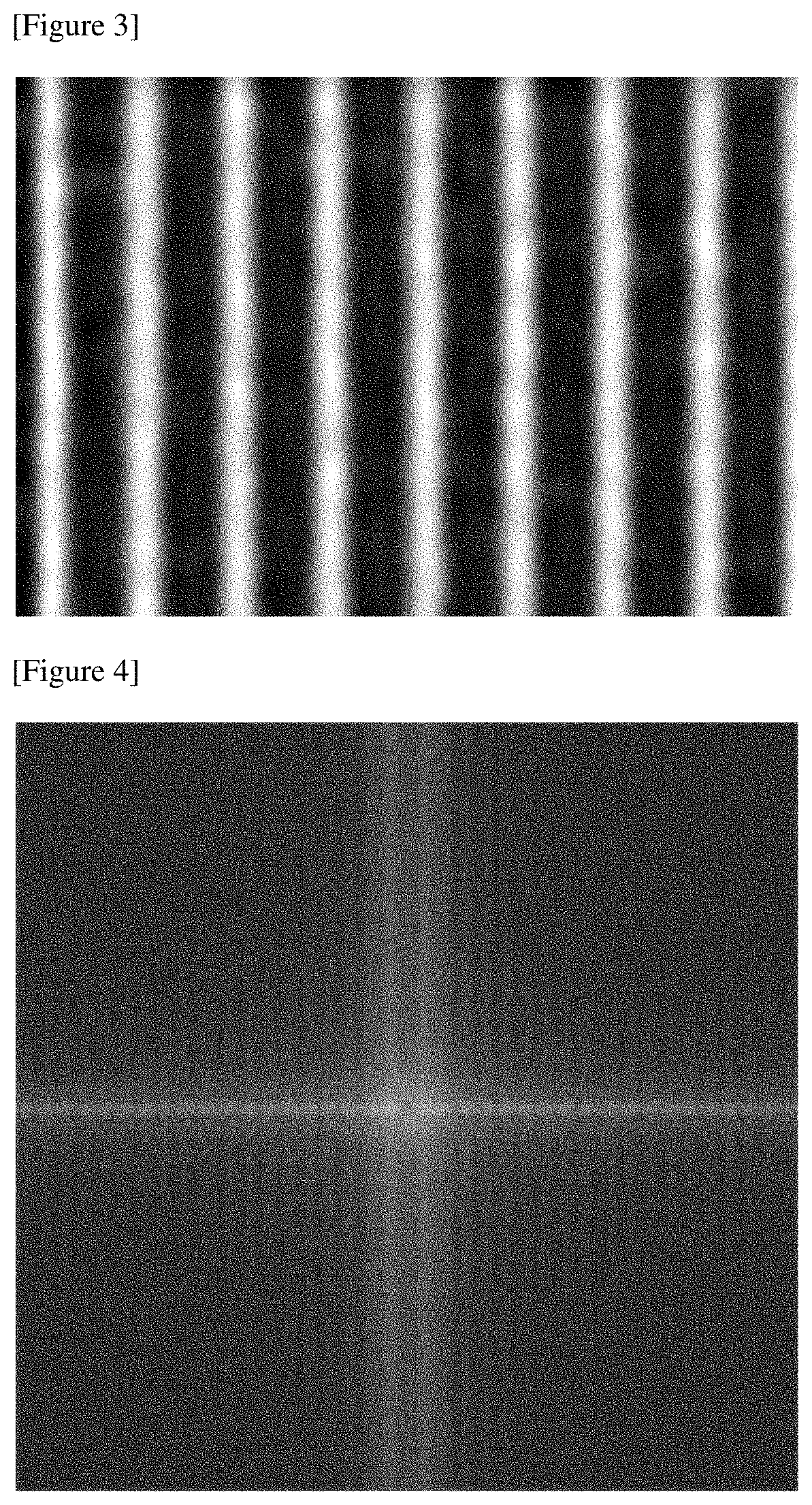
[0053]FIG. 8 is a SEM photograph of a polymer membrane formed in the above manner. The image of FIG. 8 was Fourier-transformed using image analysis software (US National Institute of Health [NIH] open source, “Image J”). FIG. 9 is the Fourier-transformed image of the polymer membrane.
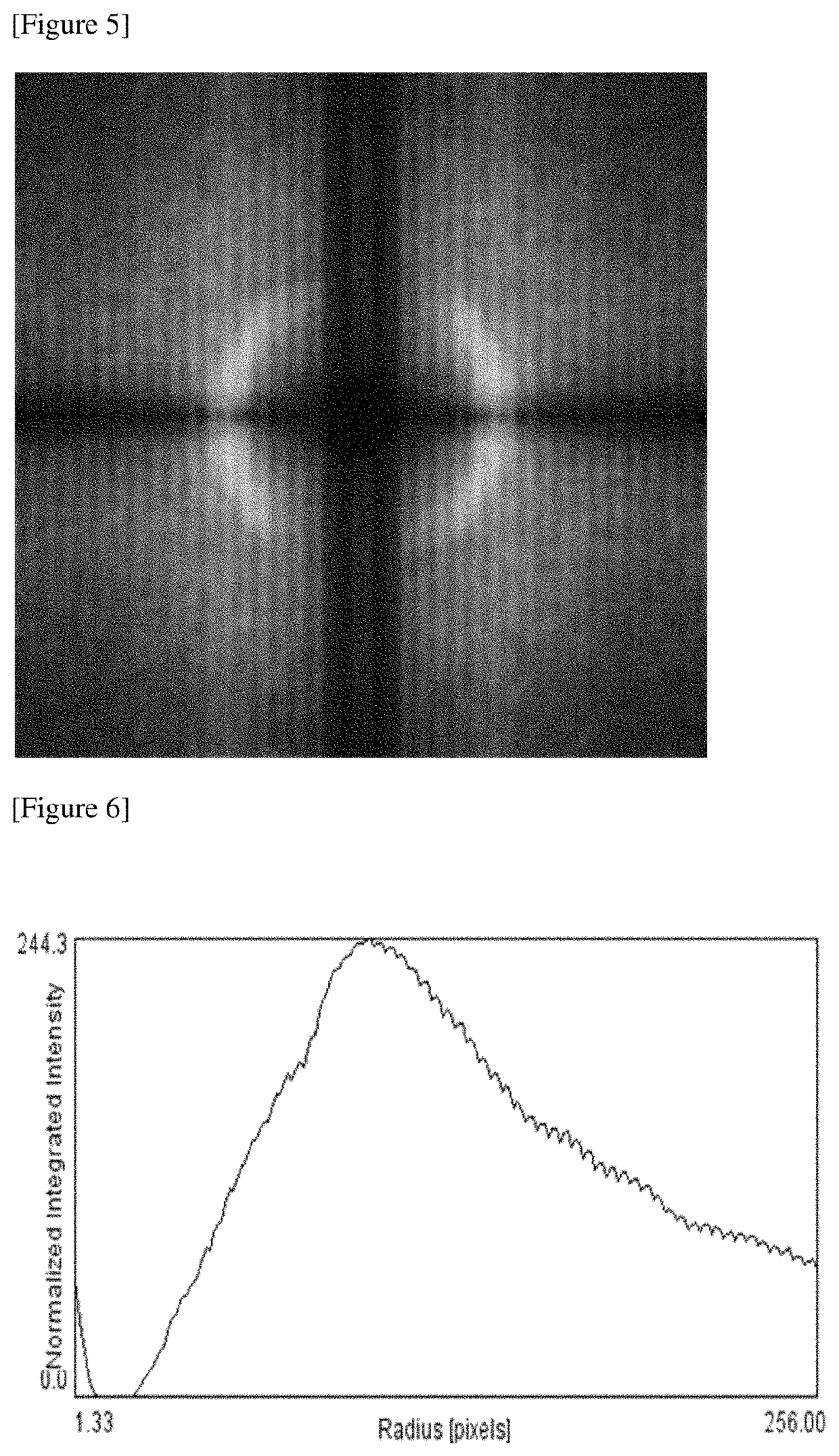
[0054]Furthermore, FIG. 10 is an image obtained by blurring the image of FIG. 8 using image analysis software (US National Institute of Health [NIH] open source, “Image J”), and FIG. 11 is an image Fourier-transforming the blurring-processed FIG. 10 using the same program.
[...
PUM
| Property | Measurement | Unit |
|---|---|---|
| distance | aaaaa | aaaaa |
| distance | aaaaa | aaaaa |
| width | aaaaa | aaaaa |
Abstract
Description
Claims
Application Information
 - R&D
- Intellectual Property
- Life Sciences
- Materials
- Tech Scout
- Unparalleled Data Quality
- Higher Quality Content
- 60% Fewer Hallucinations
Browse by: Latest US Patents, China's latest patents, Technical Efficacy Thesaurus, Application Domain, Technology Topic, Popular Technical Reports.
© 2025 PatSnap. All rights reserved.Legal|Privacy policy|Modern Slavery Act Transparency Statement|Sitemap|About US| Contact US: help@patsnap.com


