

Organic electroluminescent device
a technology of electroluminescent devices and organic materials, which is applied in the direction of organic semiconductor devices, solid-state devices, semiconductor devices, etc., can solve the problem of not specifically revealing a red light-emitting organic electroluminescent device, and achieve the effects of reducing the amount of materials used, increasing production efficiency, and reducing the thickness of the devi
- Summary
- Abstract
- Description
- Claims
- Application Information
AI Technical Summary
Benefits of technology
Problems solved by technology
Method used
Image

Examples
example
[0058][Measuring Method of Refractive Index]
[0059]In order to obtain the refractive index of the organic electroluminescent material of the present disclosure, the material of which the refractive index is to be obtained was introduced into a cell of the vacuum vapor deposition apparatus, and the pressure in the chamber of the apparatus was then controlled to 10−6 torr. Thereafter, an electric current was applied to the cell to evaporate the introduced material, thereby producing a sample having a thickness of 30 nm on a silicon wafer substrate.
[0060]The refractive index was measured using an ellipsometer. Specifically, the refractive index at a wavelength of 350 to 800 nm using UVSEL of HORIBA Ltd., as the refractive index based on 620 nm at an incidence angle of 60 degrees was used.
[0061]The measured refractive index and the calculation result of quantum dynamics calculation and molecular dynamics calculation based on molecular structure of the material were compared.
[0062][Calcul...
examples 1 to 4
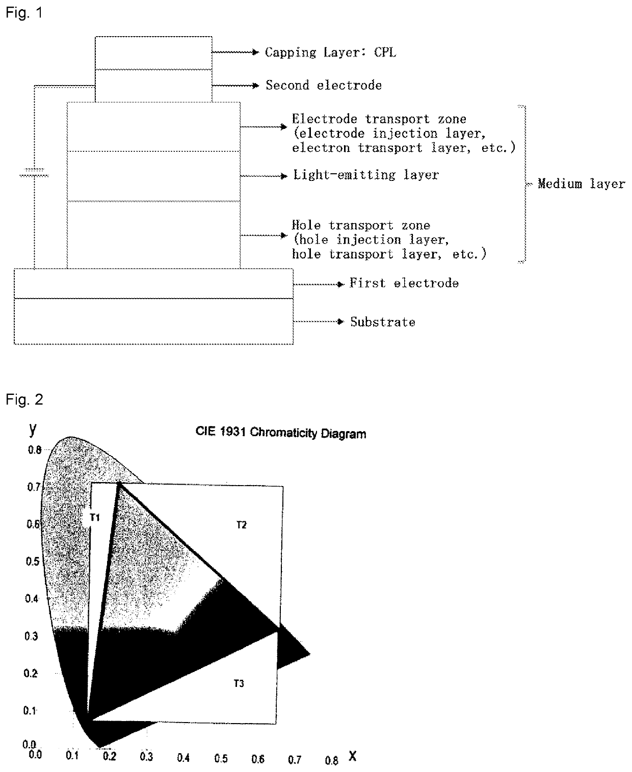
Light-Emitting OLED Device Comprising the High Refractive Index Material According to the Present Disclosure in at Least One Layer of the Hole Transport Zone
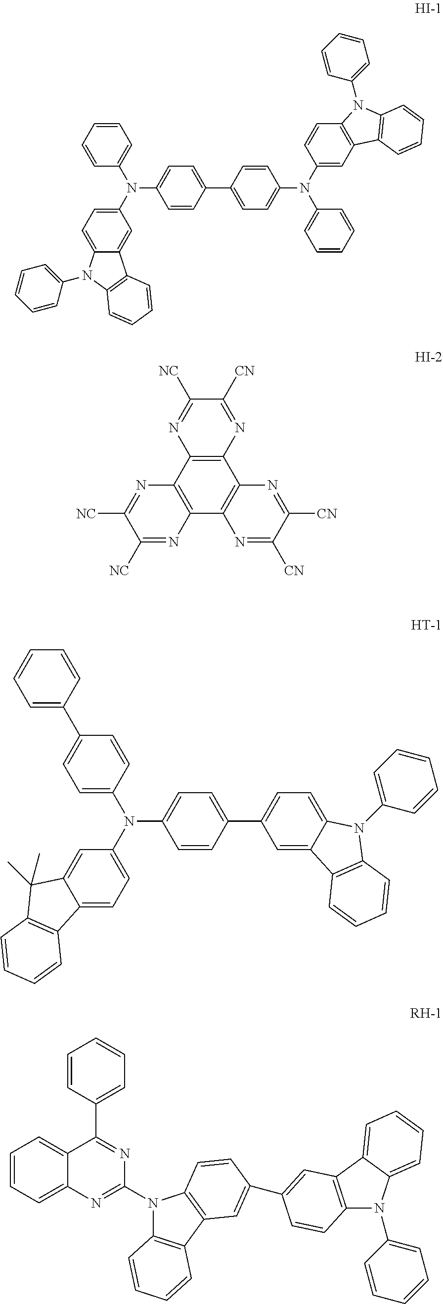
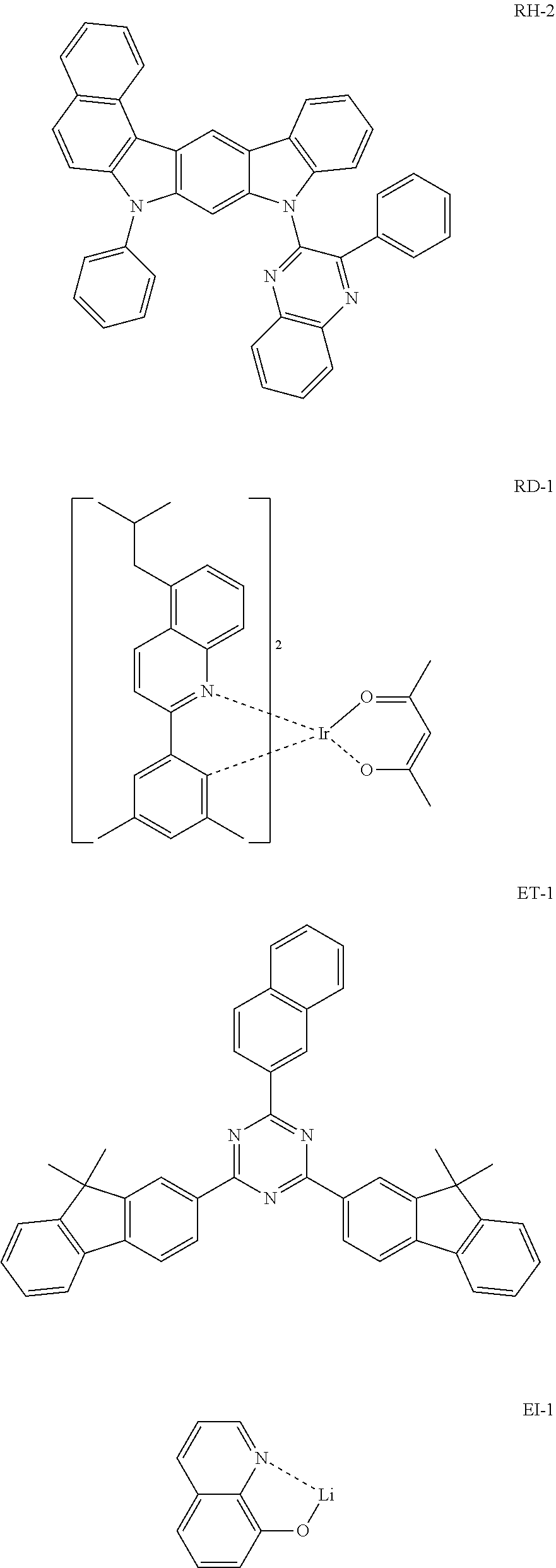
[0068]A red light-emitting OLED device according to the present disclosure was produced as follows: An ITO / Ag / ITO glass substrate of a top emission device wherein a first electrode is formed as a reflecting film was subjected to an ultrasonic washing with acetone, ethanol, and distilled water, sequentially, and then was stored in isopropanol. Next, the glass substrate was mounted on a substrate holder of a vacuum vapor deposition apparatus. Compound HI-1 was introduced into a cell of the vacuum vapor deposition apparatus, and the pressure in the chamber of the apparatus was then controlled to 10−6 torr. Thereafter, an electric current was applied to the cell to evaporate the introduced material, thereby forming a first hole injection layer having a thickness of 65 nm on the glass substrate. Compound HI-2 was then introduced into...
examples 5 and 6
Light-Emitting OLED Device Comprising the High Refractive Index Material According to the Present Disclosure in at Least One Layer of the Light-Emitting Layers
[0074]A red light-emitting OLED device according to the present disclosure was produced as follows: An ITO / Ag / ITO glass substrate of a top emission device wherein a first electrode is formed as a reflecting film was subjected to an ultrasonic washing with acetone, ethanol, and distilled water, sequentially, and then was stored in isopropanol. Next, the glass substrate was mounted on a substrate holder of a vacuum vapor deposition apparatus. Compound HI-1 was introduced into a cell of the vacuum vapor deposition apparatus, and the pressure in the chamber of the apparatus was then controlled to 10−6 torr. Thereafter, an electric current was applied to the cell to evaporate the introduced material, thereby forming a first hole injection layer having a thickness of 65 nm on the glass substrate. Compound HI-2 was then introduced in...
PUM
 Abstract
Description
Claims
Application Information