Electrical machine winding assembly and method of manufacture thereof

a technology of winding assembly and electrical machine, which is applied in the direction of windings, inorganic insulators, magnetic circuit shapes/forms/construction, etc., can solve the problems of degrading electrical insulation, overvoltage of motor terminals, and typically set limits

Active Publication Date: 2022-05-10
ROLLS ROYCE PLC
View PDF14 Cites 0 Cited by
  • Summary
  • Abstract
  • Description
  • Claims
  • Application Information

AI Technical Summary

Benefits of technology

[0015]In the first aspect the winding assembly is manufactured by first 3D printing (also known in the art as additive manufacturing) the insulation such that a winding path is defined by a channel, and then subsequently introducing an electrically conducting material into the channel to form the winding. Advantageously, 3D printing can be carried out with a wide range of materials and the shape and location of the channel defining the winding path can be precisely controlled in the 3D printing process. Many electrically conducting materials are difficult to 3D print but this issue may be overcome by 3D printing the insulation first and then subsequently adding the electrically conducting material, as per the first aspect. By employing a 3D printing process to make the electrically insulating body, the shape or cross section of the channel can be made precisely as desired in order to accommodate an insulation gradient where partial discharge risk is mitigated by increased insulation thickness on initial turns of a coil. Further, the electrically insulating body can be shaped around the channels in order to improve heat transfer to the environment, e.g. by forming the body with fins or other projections to increase surface area for heat exchange. This helps to manage heat transfer from the coil to the environment and also manages power loss within the windings.
[0040]The electrically insulating body may be formed of a ceramic material. The electrically conducting material may be copper. Ceramic is an excellent electrically insulator and copper is an excellent electrical conductor. Since ceramic has a higher melting point than conventional polymer insulation, an electrical machine employing a winding assembly according to the first aspect and with ceramic insulating material can operate in a high temperature environment without requiring cooling.

Problems solved by technology

These limitations are typically set by the insulation system used on the windings / coils in the electrical machine, which may be a generator or a motor, for example.
However they are not as flexible, they suffer from thermal expansion mismatch with the copper wire and they can crack with rapid heating (thermal shock).
For one or more of these reasons, whilst ceramic insulated wires are in principle available, they are rarely chosen for use in electrical machine applications as the lifetime can be short due to failure modes such as crackling, thermal shock, etc.
Depending on the control characteristics (gate resistors, capacitors, voltage commands) and the pulse width modulation (PWM) scheme adopted, combined with the impedance of the cable leading to the electric motor and the winding itself, repetitive overvoltage on the motor terminals may result.
The use of PWM may degrade the electrical insulation between turns of the motor windings and possibly reduce the motor lifetime.
Over time, partial discharge can degrade the insulation to the extent that it will result in a full short circuit failure of the electrical machine.
Partial discharge is particularly likely to be a problem in high frequency converter fed electrical machines where the voltage rise time for each energisation of a pole is very short (i.e. a large value of dV / dt).

Method used


Image

  • Electrical machine winding assembly and method of manufacture thereof
  • Electrical machine winding assembly and method of manufacture thereof
  • Electrical machine winding assembly and method of manufacture thereof

Examples


Embodiment Construction

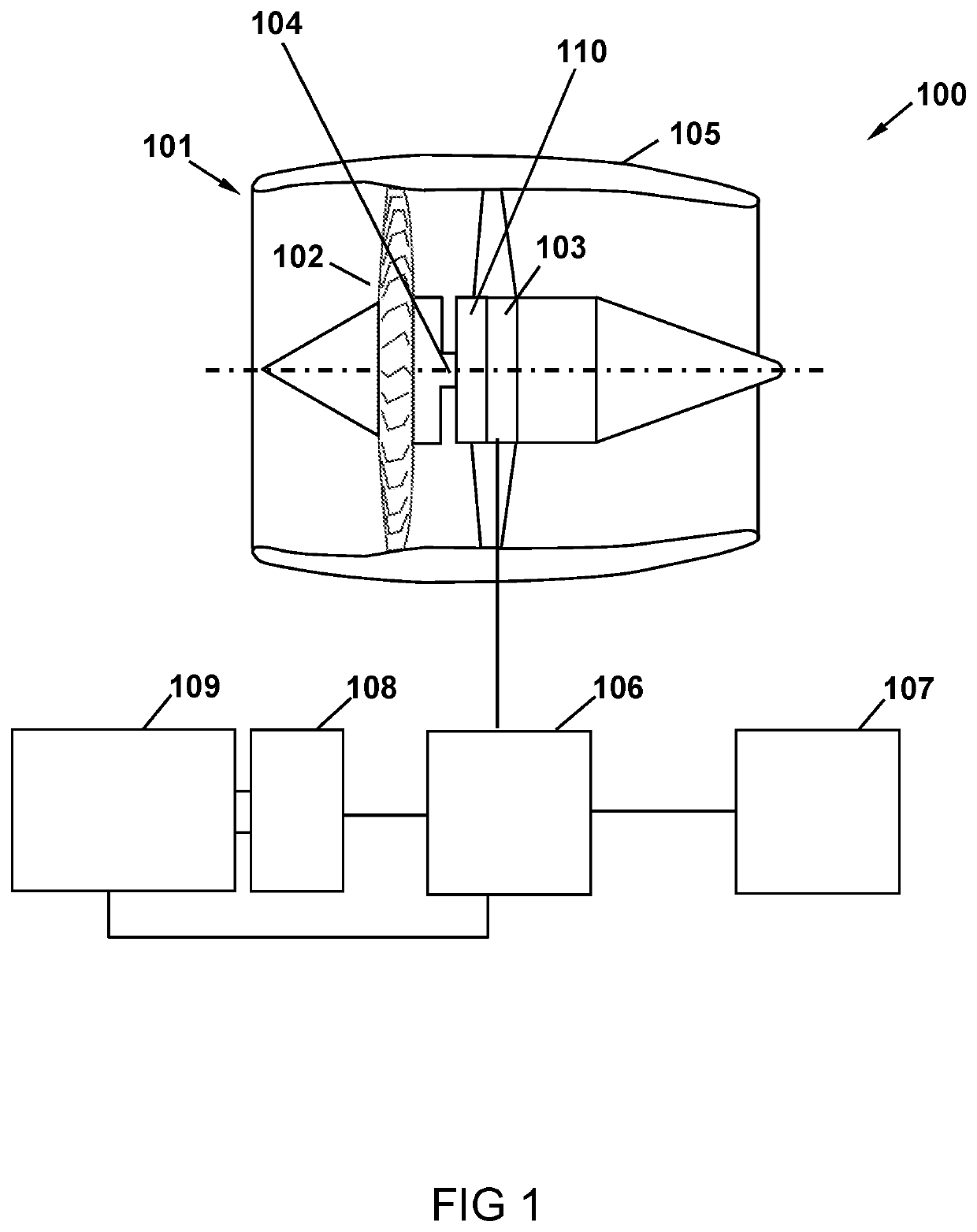
[0055]A schematic diagram of a basic hybrid electric aircraft propulsion system 100 is shown in FIG. 1. An electric propulsion unit, or engine, 101 comprises a fan 102 connected to an electric motor 103 by a central shaft 104. As with a conventional gas turbine engine, the engine 101 comprises a nacelle 105 surrounding the fan 102 and motor 103. The engine 103 is provided with electric power via power electronics in a controller 106, which is connected to an electric storage unit 107, which may include a battery, a supercapacitor or a combination of the two.

[0056]The controller 106 is also connected to a generator 108 and a gas turbine engine 109. The gas turbine engine 109 drives the generator 108 to generate electric power, which the controller 106 distributes between the electric storage unit 107 and the electric motor 103. Under some conditions, the electric motor 103 may also act as a generator, for example when a reduction in thrust is demanded and the forward movement of the ...


PUM

PropertyMeasurementUnit
temperatureaaaaaaaaaa

Abstract

A method of manufacturing a winding assembly for an electrical machine, the method comprising: selecting (S1) a mathematical function defining the spatial separation between adjacent turns of a winding path, the mathematical function dependent on one or more parameters of the electrical machine and / or of the anticipated operating environment of the electrical machine; forming (S2), by three-dimensional, 3D, printing, an electrically insulating body comprising a channel defining the winding path in accordance with said function, the channel having an inlet and an outlet; heating (S3) the electrically insulating body to a temperature above the melting point of an electrically conducting material; flowing (S4) the electrically conducting material through the inlet to the outlet to fill the channel; and cooling the electrically insulating body to solidify the electrically conducting material within the channel, thereby forming said winding assembly.

Description

CROSS-REFERENCE TO RELATED APPLICATIONS[0001]This application is based upon and claims the benefit of priority from British Patent Application No. GB 1815304.9, filed on 20 Sep. 2018, the entire contents of which are herein incorporated by reference.BACKGROUNDTechnical Field[0002]This disclosure relates to electrical machines and in particular to a winding assembly for an electrical machine and a method of manufacturing same.Description of the Related Art[0003]Conventional electrical machine design has certain temperature limitations. These limitations are typically set by the insulation system used on the windings / coils in the electrical machine, which may be a generator or a motor, for example. Electrical machine windings may be on the rotor, on the stator or on both, and typically comprise several turns of an electrically conducting wire, such as copper, wound around a soft magnetic tooth (pole). The electrically conducting wire is coated with an electrically insulating medium to...

Claims


Application Information

Patent Timeline
Patent Type & Authority Patents(United States)
IPC IPC(8): H02K15/04H01B3/12H02K1/18H02K3/02H02K3/30H02K3/34H02K3/50H02K15/12B33Y80/00
CPCH02K15/0407H01B3/12H02K1/18H02K3/02H02K3/30H02K3/34H02K3/50H02K15/12B33Y80/00H02K15/00H02K3/04H02K3/18H02K3/32H01F5/02H01F41/125H02K15/08
Inventor KHAN, JAMEEL B.LAMBOURNE, ALEXISSMITH, ALEXANDER C.
Owner ROLLS ROYCE PLC
Why Eureka
Try Eureka