

Receiver architectures with parametric circuits
a receiver architecture and parametric circuit technology, applied in the field of radio frequency (rf) receiver architecture and circuitry, can solve the problems of insufficient power generation or sensitivity of conventional transceivers for reliable communication standing alon
- Summary
- Abstract
- Description
- Claims
- Application Information
AI Technical Summary
Benefits of technology
Problems solved by technology
Method used
Image

Examples
first embodiment
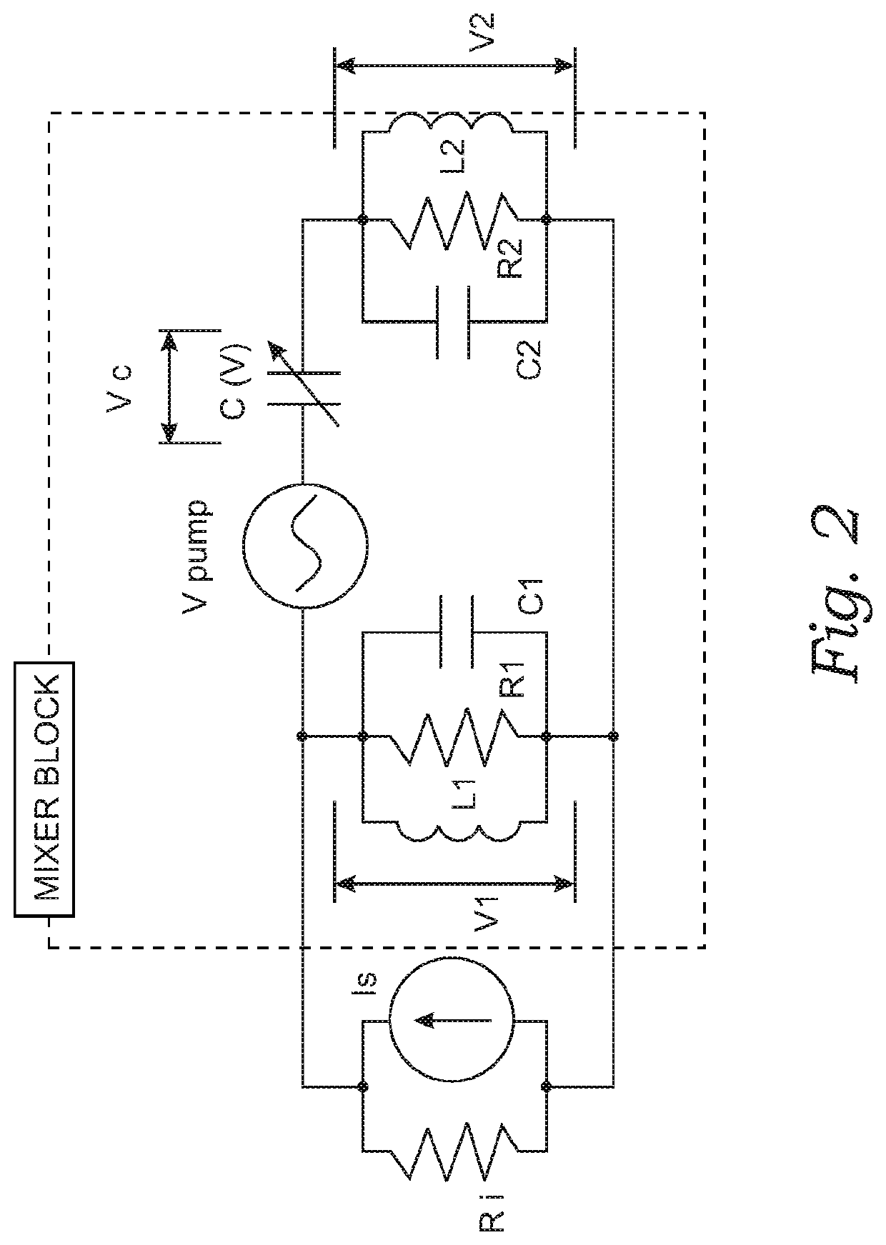
[0027]FIG. 2 is a simplified electrical schematic diagram representing an equivalent circuit of an RF receiver parametric circuit mixer block according to the invention. The mixer block (MIXER BLOCK) comprises two parallel resonant circuits which are connected together in series via a varactor diode which is shown as a variable non-linear capacitor C(V) for simplicity. Ri represents an intrinsic resistance of an RF signal source with current Is which provides an input to the mixer block. R1 is a resonant resistance of an input RF circuit comprised of inductor L1 and capacitor C1 with resonant or center frequency ω1, while R2 is a resonant resistance of an output IF circuit comprised of inductor L2 and capacitor C2 with resonant or center frequency ω2. Both resonant circuits are connected in parallel to a useful load. Resonance occurs in a parallel RLC circuit when the total circuit current is “in-phase” with the supply voltage as the two reactive components cancel each other out. At...
second embodiment
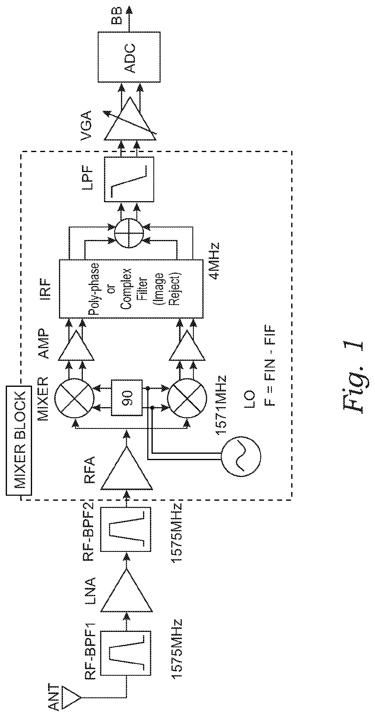
[0064]FIG. 6 is a schematic depiction of a low-IF radio frequency (RF) receiver architecture with two degenerate parametric circuits of the invention. FIG. 6 illustrates a low-IF architecture for a GPS / Galileo receiver with two degenerate parametric circuits. An input signal from an antenna is applied to a first RF filter RF-BPF1 with center frequency FIN chosen at 1575 MHz to filter out-of-band blocking signals. In this embodiment the IF frequency FIF is chosen at 8 MHz to operate properly with both 2 MHz wide (GPS) and 4 MHz wide (Galileo) signals. A local oscillator LO frequency F is chosen such that F=2FIN−2FIF=3134 MHz which is applied to a first parametric circuit PAR1. Local oscillator signal leakage rejection through an antenna is greatly simplified due to the large frequency separation between the received and local oscillator signals. A second RF filter RF-BPF2 at the output of first parametric circuit PAR1 is tuned for a center frequency of F−FIN=1559 MHz. In this archit...
third embodiment
[0066]FIG. 7 is a schematic depiction of a low-IF radio frequency (RF) receiver architecture with one degenerate and one non-degenerate parametric circuit of the invention. FIG. 7 illustrates a low-IF architecture for addressing low noise figure for the overall receiver chain of a GPS / Galileo receiver with one non-degenerate parametric circuit and one degenerate parametric circuit. An input signal from an antenna is applied to a first RF filter RF-BPF1 with center frequency FIN chosen at 1575 MHz to filter out-of-band blocking signals. In this embodiment the IF frequency FIF is chosen at 8 MHz to operate properly with both 2 MHz wide (GPS) and 4 MHz wide (Galileo) signals. A local oscillator LO frequency F is chosen such that F=2FIN+2FIF=3166 MHz. The local oscillator frequency is divided by two and applied as a pump frequency of F / 2 or 3166 / 2=1583 MHz to a first parametric circuit PAR1. The second RF filter at the output of first parametric circuit RF-BPF2 is tuned for a center fr...
PUM
 Abstract
Description
Claims
Application Information