
Device and method for circulating liquids

a technology of liquid circulation and liquid tubes, applied in the direction of positive displacement liquid engines, pump control, dynamo-electric machines, etc., can solve the problems of limited lifetime of paramagnetic liquid tubes, low reynolds number, and limited stable geometries of microfluidic circuitry, so as to limit the negative impact of mechanical moving parts

Active Publication Date: 2022-09-06
UNIVERSITY OF STRASBOURG +2
View PDF14 Cites 0 Cited by
  • Summary
  • Abstract
  • Description
  • Claims
  • Application Information

AI Technical Summary

Benefits of technology

[0063]In one embodiment, said fluid comprises miscible or immiscible liquids. Advantageously, said more-paramagnetic liquid and said less-paramagnetic liquid are immiscible liquids. When said more-paramagnetic liquid and said less-paramagnetic liquid are immiscible, there will be limited or even no mixing between the two liquids thereby limiting or even eliminating contamination effects of components from one liquid to the other.
[0074]In one embodiment, said more-paramagnetic liquid comprises one or more surfactants. Advantageously, a surfactant helps to lower the surface tension of the more-paramagnetic liquid with the less-magnetic liquid.
[0076]In one embodiment, both the less- and the more-paramagnetic liquids contain one or more surfacants. Advantageously, the use of the latter multiple surfactant approach can lead to very low (below 1 mN m−1) surface tensions.
[0112]Advantageously, a device and method according to the invention provides low shearing fluidic channels. For the pumping application, this is an additional benefit, since it would render the pump suitable for biological applications.
[0113]Advantageously, a device and method according to the invention provide a good flexibility regarding pumping rate and pressure. Particularly, device and method according to the invention have advantages over state of art devices at low flow rate and pressure range. To achieve low flow rate or pressure, the moving part of pumps need to run at very slow rate. For example, for peristaltic pump with rollers, the rotation speed needs to be reduced to achieve slow flows. Then it is difficult to remove pulsation of the flow. In a device and method according to the invention, the number and the strength of pinching points is controlled by the magnetic field. To reduce the flow rate or pressure, one embodiment is to decrease the strength of magnetic field instead of decreasing the frequency of pinching. This makes the device and method according to the invention stronger than current state-of-art for making pulsation-free flow. In addition, the pump cost (in components) of a device and method according to the invention is much lower than peristaltic pumps of the prior art.

Problems solved by technology

Several drawbacks have so far prevented the adoption of the liquid tube technology especially in the field of microfluidics, namely i) the need for a large electromagnet to create the external field, ii) limited lifetime of the paramagnetic liquid tubes, due to diffusion of ions into the medium (decreasing the susceptibility difference), iii) toxicity of paramagnetic ions, and iv) limited stable geometries of the microfluidic circuitry.
A more challenging limitation of microfluidic technology is the change in fluid behaviour at small scales, leading to laminar flow at low Reynolds number.
Passive and active microfluidic mixers have been designed to accelerate mixing, but are challenging to incorporate into devices since they require complex 3D geometries or miniaturized actuation.
Lastly, there are several key practical issues limiting the reliability, re-usability and long-term stability of microfluidic devices such as fouling or adsorption onto the walls of the channel due to the high surface-to-volume ratio, clogging of channels due to dust particles, and leaking at high fluid pressure due to faulty connections or device delamination.
In addition, the seminal work of Coey et al. also demonstrated that the magnetic field force prevents convection around the liquid tube, but does not inhibit vorticity, and thus mixing, within the tube or anti-tube.
While Coey's work was an important milestone toward a new type of microfluidics, there were a number of challenges remaining to achieve viable microfluidic applications.
In short, the system was promising but not usable for life science applications.

Method used


Image

  • Device and method for circulating liquids
  • Device and method for circulating liquids
  • Device and method for circulating liquids

Examples


example 1

queous Liquid Anti-Tubes

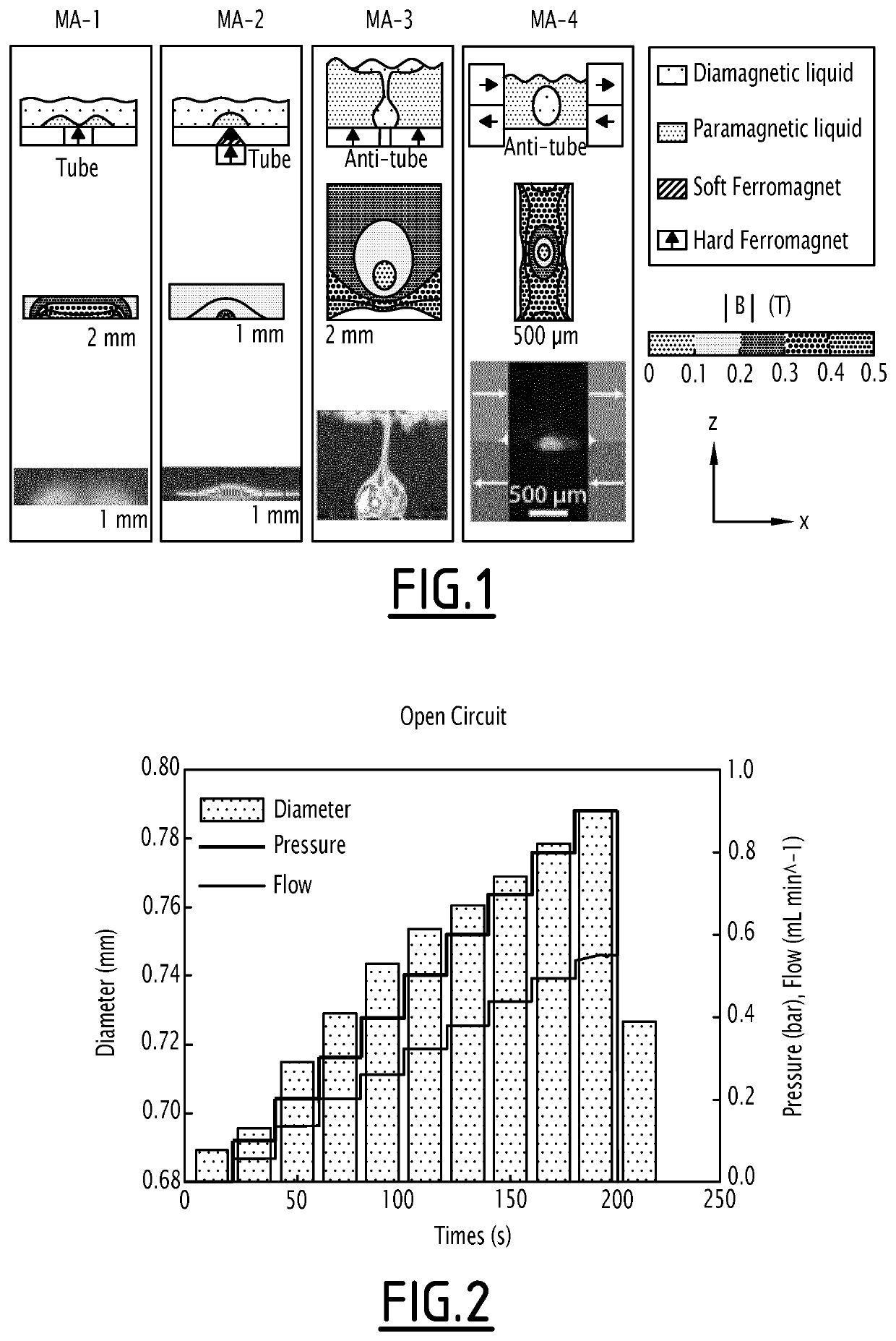
[0153]A range of different magnet arrangements have been used to stabilize paramagnetic liquid anti-tubes (i.e., a tube of a diamagnetic liquid within a paramagnetic fluid). The paramagnetic liquid in this section is made by dissolving holmium chloride (HoCl3) in water, whereas the diamagnetic (less paramagnetic) liquid is pure water. In all cases small commercially available NdFeB magnets were used to fabricate the magnet arrangements and the tube was visualized by confocal microscopy (using Rhodamine B as a dye). For each of four magnet arrangements MA1-4 the following three types of information are shown in FIG. 1.

[0154]In FIG. 1:

[0155]a) Schematic of liquid tube and anti-tube confinement for four magnet arrangements, the first two stabilize tubes of paramagnetic HoCl3 in water, the last two stabilize anti-tubes of water or LaCl3 in HoCl3; b) analytically evaluated contour plots of |B| for the geometries; c) confocal cross-section fluorescence images of rh...

example 2

ily Anti-Tubes

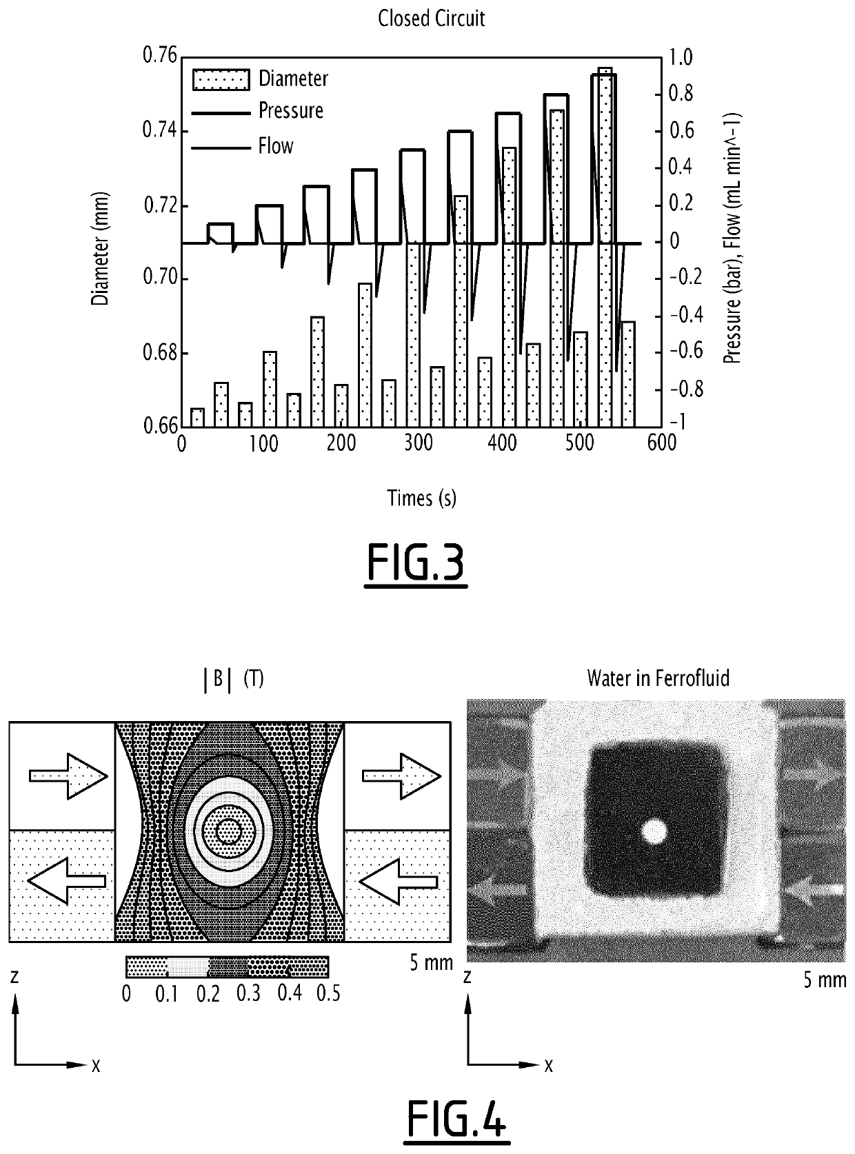
[0158]The inventors noted that anti-tubes described in example 1 have only a limited life-time when the paramagnetic liquid is an aqueous solution of paramagnetic ions and the less-paramagnetic liquid is pure diamagnetic water, due to diffusion of Ho3+ ions across the paramagnetic / diamagnetic boundary. The ion diffusion reduces the difference in magnetic susceptibility between the two initially well-defined regions, which in turn lowers the magnetic pressure and bulk forces. However, when implementing two liquids that are immiscible by replacing the aqueous paramagnetic liquid by an (APG 300, Ferrotec) oil-based ferrofluid, any transport across the boundary was prevented, and thus leads to anti-tubes that are stable for months. The anti-tube diameter can be measured from the side-view of the device using a stereoscope in transmission mode. To characterize the behaviour of the anti-tube a series of pressure experiments was performed. Firstly, a defined pressure was appl...

example 3

f Elements Generating a Magnetic Field

[0159]3.1. Quadrupole

[0160]The inventors have designed magnetic arrays to form an anti-tube by magnetic field simulations (using either finite element methods or analytical expressions using SciPy) and prototyping (using a 3D printer). With a quadrupole magnet arrangement it is possible to achieve stable anti-tubes of virtually any diamagnetic liquid that is immiscible with the paramagnetic medium as shown in FIG. 4.

[0161]A commercial ferrofluid (black colour) was used as paramagnetic liquid and water as diamagnetic liquid. Water that was flowed through the ferrofluid remained clear and transparent further supporting the stability of the anti-tube. Water flows freely through the black oily ferrofluid without being contaminated by the paramagnetic liquid. In other words, the combination of the quadrupole magnets and the ferrofluid results in a channel with liquid walls.

[0162]3.2. Single Sided Designs

[0163]Single sided designs are suitable when bu...


PUM

PropertyMeasurementUnit
sizeaaaaaaaaaa
sizeaaaaaaaaaa
pressuresaaaaaaaaaa

Abstract

Disclosed is a device including at least one circulating zone and at least one fluid including at least one more-paramagnetic liquid and at least one less-paramagnetic liquid forming a liquid-liquid interphase, the device including at least one element generating, in the circulating zone, a magnetic field, wherein the less-paramagnetic liquid is surrounded by the more-paramagnetic liquid in the circulating zone or wherein the more-paramagnetic liquid is surrounded by the less-paramagnetic liquid in the circulating zone. Also disclosed is a method including circulating at least one less-paramagnetic liquid inside one or more circulating zones of a device including at least one circulating zone and at least one more-paramagnetic liquid in the circulating zone.

Description

[0001]The invention relates to a device and a method for circulating liquids.[0002]In particular, the invention relates in particular to a device and a method for circulating a less-paramagnetic liquid into an enclosing more paramagnetic liquid or for circulating a more-paramagnetic liquid into an enclosing less paramagnetic liquid.PRIOR ART[0003]Transporting fluids (gas or liquid) from point A to B in a controlled manner has been a vital technology underlying much science and technology. A pump is a device invented for transporting fluids by mechanical action. A wide variety of pumps have been invented depending on the type and volume of fluids one desires to transport, which can be largely classified as positive displacement pumps or centrifugal pumps (also called rotodynamic pumps). Positive displacement pumps squeeze fluid directly while centrifugal pumps speed up fluids and convert the kinetic energy to pressure.[0004]Magnetic fields are already exploited in many areas of resea...

Claims


Application Information

Patent Timeline
Patent Type & Authority Patents(United States)
IPC IPC(8): F04B17/00F04B43/10F04B43/12F04B49/06H02K44/00
CPCF04B17/00F04B43/10F04B43/12F04B49/06H02K44/00F05B2210/11
Inventor HERMANS, THOMASCOEY, JOHN MICHAEL DAVIDDUNNE, PETERDOUDIN, BERNARD
Owner UNIVERSITY OF STRASBOURG
Learn More