Method of forming an ESD protection device

Inactive Publication Date: 2001-08-02
VANGUARD INTERNATIONAL SEMICONDUCTOR CORPORATION
View PDF0 Cites 14 Cited by
  • Summary
  • Abstract
  • Description
  • Claims
  • Application Information

AI Technical Summary

Benefits of technology

[0010] The present invention relates to the method of forming an ESD protection device. According to the present invention, an NMOS transistor is formed and a P.sup.+ ESD protection implantation is applied to reduce the breakdown voltage of PN junction; furthermore, extra N-wells are formed in the source / drain regions of the NMOS transistor to further reduce the junction capacitance. Firstly, a P-well, N-wells, and isolations are formed in a semiconductor substrate. The N-wells are the key features of the present invention that the design and layout of the photo mask are amended so that N-wells are also formed in a part of the source / drain regions of the NMOS transistor. As a result, the demand of reducing junction capacitance is achieved without adding any photo mask.
[0012] A key feature of this present invention is that the ESD protection regions are formed under the source / drain regions by means of a P.sup.+ ESD protection implantation to form a heavily-doped PN junction with relatively low breakdown voltage and quick response speed, so as to achieve the purpose of protecting the interior devices. Furthermore, due to adding the N-wells in the NMOS transistor according to the present invention, the area of high-doped PN junction is largely decreased so as to reduce the total junction capacitance on the drain of the NMOS devices.

Problems solved by technology

When such a high voltage is applied to the pins of an IC package, its discharge (referred to as electrostatic discharge; ESD) can cause serious damage on the gate oxide of the devices.
The ESD event may cause sufficient damage to produce immediate destruction of the device, or it may weaken the oxide strength.
Therefore, it is a fairly important issue for IC industries to reduce the PN-junction's breakdown voltage of the ESD protection devices.
However, this process not only needs an extra photo mask for photolithography process, but also increases the junction capacitance so that the transmission speed for input signals becomes much slower.

Method used


Image

  • Method of forming an ESD protection device
  • Method of forming an ESD protection device
  • Method of forming an ESD protection device

Examples


second embodiment

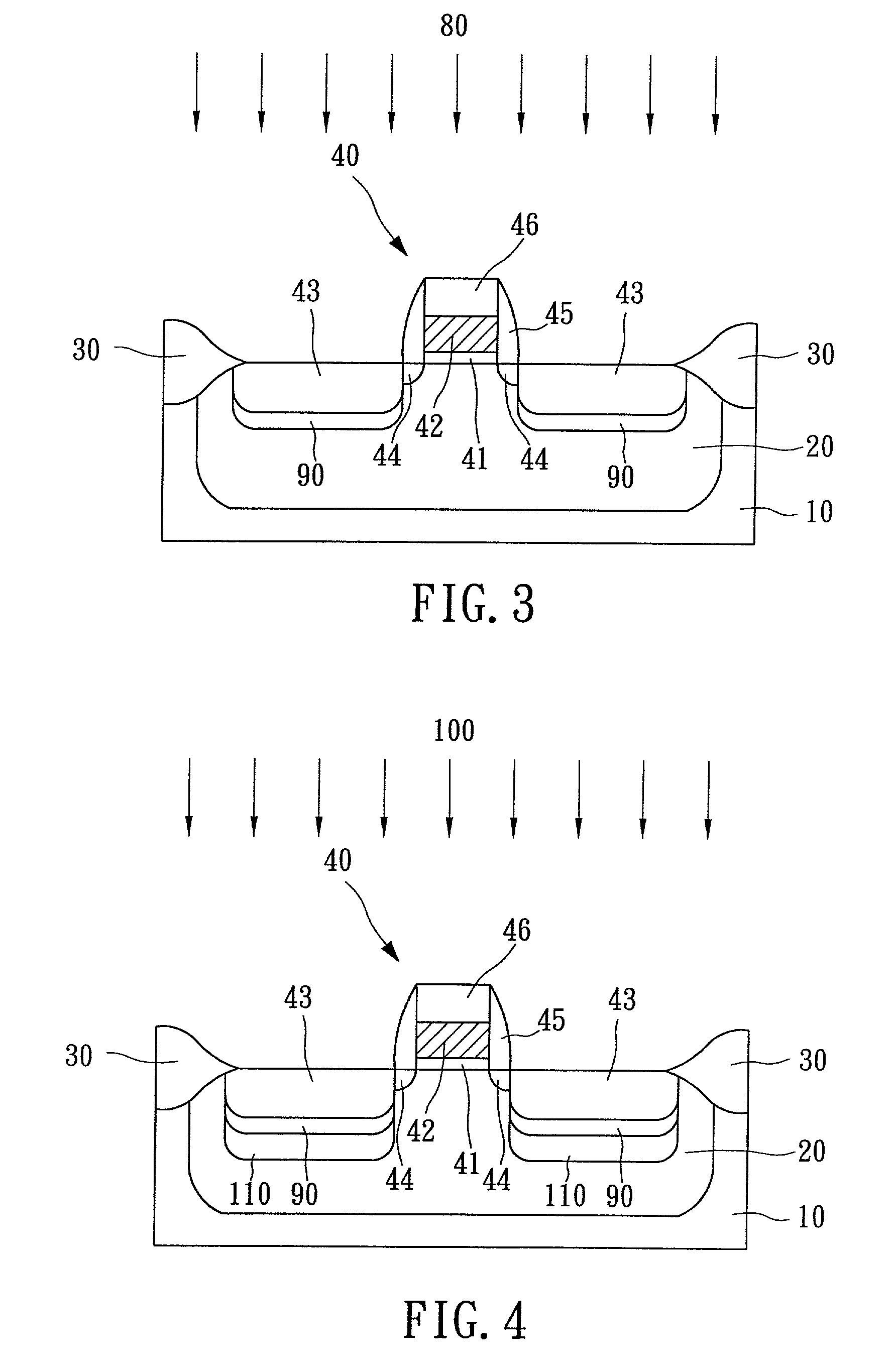
[0027] An additional N.sup.+ implantation is applied to the source / drain regions in this embodiment in order to increase the depth of the PN junction. The devices obtained by this embodiment can not only reduce the breakdown voltage and increase response speed of PN junction as by the first embodiment, but also further enhance the ESD-current capability. In the following description for this embodiment, the processes and schematic diagrams for forming the P-well and MOS structure on the silicon substrate are totally the same with those in the first embodiment and thus not repeated. In addition, similar parts will be marked by similar numerals according to FIG. 1 to facilitate reading of the description.

[0028] Referring now to FIG. 3, an addition N.sup.+ junction-deepening implantation 80 is applied to form deeply-doped regions 90 under the source / drain regions 43. The deeply-doped regions 90 are formed via ion implantation of arsenic or phosphorous ions at an energy between 50 to 12...

third embodiment

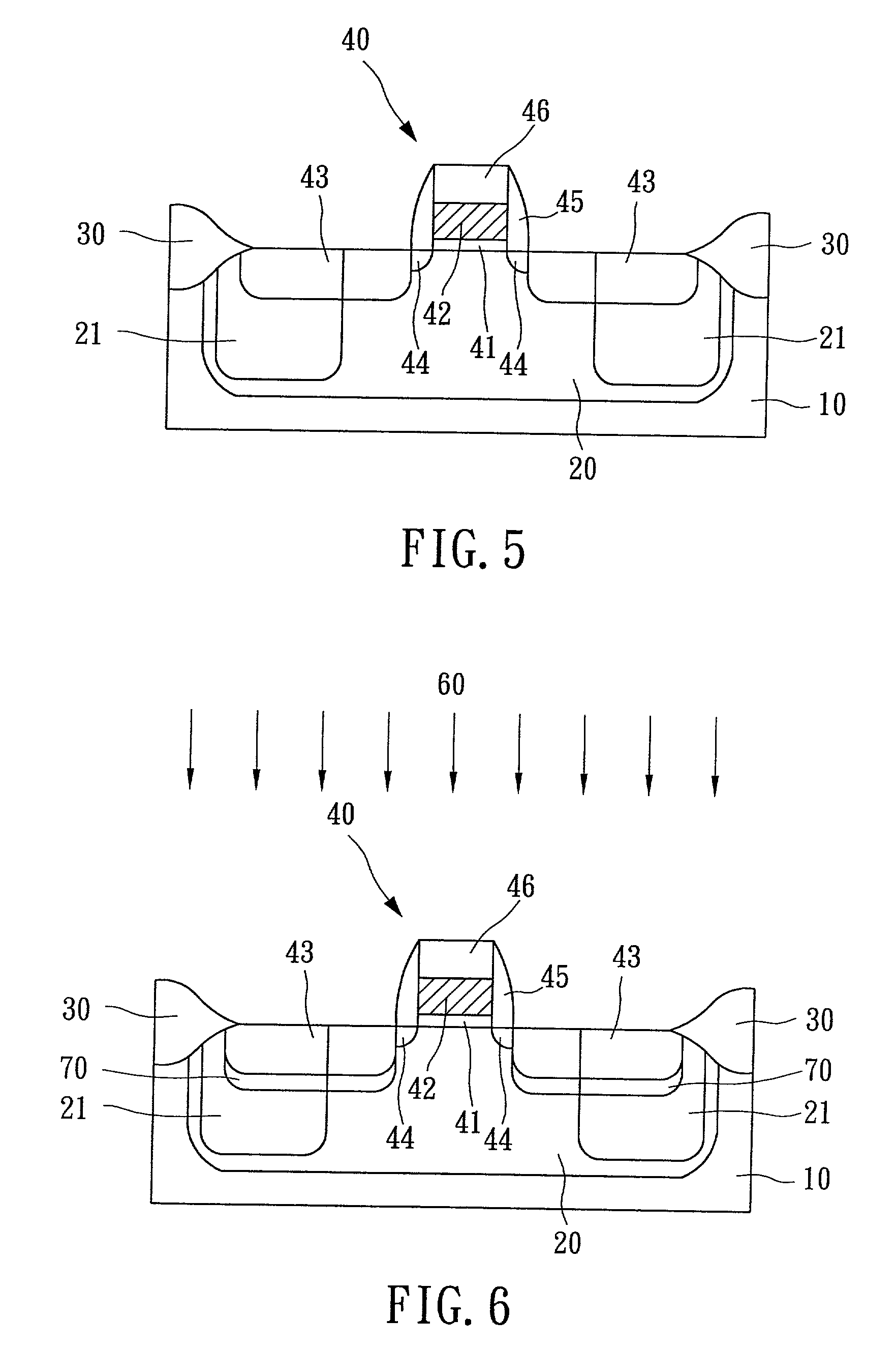
[0032] An additional N.sup.+ implantation is applied to the source / drain regions in this embodiment in order to reduce the capacitance of PN junction. The devices obtained by this embodiment can not only reduce the breakdown voltage and increase response speed of PN junction as by the first embodiment, but also resolve the capacitance-increasing issue due to the ESD protection implantation.

[0033] Referring firstly to FIG. 5, a P-well 20 and N-wells 21 are formed in a semiconductor substrate 10 by using conventional photolithography and ion-implantation procedures. Next, isolations 30 are formed to separate each active region. The isolations 30 could be conventional LOCOS (Localized Oxidation Isolation) or STI (Shallow Trench Isolation).

[0034] The N-wells 21 are the key features of the present invention. In the conventional IC technology, the N-well is used for forming PMOS and the P-well is used for NMOS. Nevertheless, the design and layout of the photo mask according to this embodi...


PUM


Abstract

The invention discloses a method of forming an ESD protection device without adding the extra mask layers into the traditional CMOS process. At first, P-wells, N-wells, and isolations are formed in a semiconductor substrate. Next, an NMOS transistor with a gate dielectric layer, a gate electrode, source / drain regions, lightly doped source / drain regions, and insulator spacers is formed on the substrate. Particularly, N-wells are also formed in a part of the source / drain regions of the NMOS transistor. Thereafter, ESD protection regions are formed under the source / drain regions by performing P+ ESD protection implantation. Such ESD protection device has a low junction breakdown voltage, quick response speed, and a small junction capacitance.

Description

[0001] 1. Field of the Invention[0002] The present invention is a continuation-in-part (CIP) of U.S. patent application Ser. No. 09 / 488,786. The present invention relates to a method of forming an ESD protection device, more particularly, to a method of forming an ESD protection device with low trigger voltage and small junction capacitance, but without adding any extra mask layer into the conventional CMOS process.[0003] 2. Description of the Prior Art[0004] The present invention is a continuation-in-part (CIP) of U.S. patent application Ser. No. 09 / 488,786. The input signals to a MOS IC are fed to the gate electrodes of MOS transistors. If the voltage applied to the gate insulator becomes excessive, the gate oxide will be broken down. The dielectric breakdown strength of SiO.sub.2 is approximately in the range between 1E7 to 2E7 V / cm. According to a MOS device manufactured by means of the deep-submicron technology (such as 0.18 um technology), the gate oxide has a thickness only a...

Claims


Application Information

Patent Timeline
IPC IPC(8): H01L21/8238H01L27/02H01L29/06H01L29/08
CPCH01L21/8238H01L27/0266H01L29/0626H01L29/0847
Inventor LIN, GEENG-LIHKER, MING-DOU
Owner VANGUARD INTERNATIONAL SEMICONDUCTOR CORPORATION
Why Eureka
Try Eureka