Intersystem crossing agents for efficient utilization of excitions in organic light emitting devices

a technology of organic light emitting devices and inter-system crossing agents, which is applied in the direction of organic semiconductor devices, thermoelectric devices, luminescent compositions, etc., can solve the problems of wasting energy in the triplet state, slow and inefficient luminescence, and few other problems

Inactive Publication Date: 2002-01-24
THE TRUSTEES FOR PRINCETON UNIV +1
View PDF0 Cites 79 Cited by
  • Summary
  • Abstract
  • Description
  • Claims
  • Application Information

AI Technical Summary

Benefits of technology

[0061] At the most general level, the present invention is directed to organic light emitting devices comprising an emissive layer wherein the emissive layer comprises an emissive molecule, with a host material (wherein the emissive molecule present as a dopant in said host material) which molecule is adapted to luminesce when a voltage is applied across a heterostructure, wherein the emissive molecule is selected from the group of phosphorescent or fluorescent organic molecules and wherein the device comprises a molecule which can function as an intersystem crossing agent ("ISC molecule") which improves the efficiency of the phosphorescence or fluorescence relative to the situation where the ISC molecule is absent. It is preferred that the emissive molecule and the intersystem crossing molecule be different and it is preferred that there be substantial spectral overlap between the emissive molecule and the intersystem crossing molecule.

Problems solved by technology

For example, if the symmetry of an exciton is different from that of the ground state, then the radiative relaxation of the exciton is disallowed and luminescence will be slow and inefficient.
However, only a very few have been identified which are also capable of efficient room temperature phosphorescence from triplets.
Thus, in most fluorescent dyes, the energy contained in the triplet states is wasted.
This typically restricts the Forster mechanism to transfers between singlet states.
Unfortunately, such systems are affected by competitive energy transfer mechanisms that degrade the overall efficiency.
Once excitons reach the guest triplet state, they are effectively lost since these fluorescent dyes typically exhibit extremely inefficient phosphorescence.
There are issues with the use of phosphorescence.
It has been noted that phosphorescent efficiency can decrease rapidly at high current densities.
It may be that long phosphorescent lifetimes cause saturation of emissive sites, and triplet-triplet annihilation may also produce efficiency losses.
Another issue is that triplet diffusion lengths are typically long (e.g., >1400.ANG.) compared with typical singlet diffusion lengths of about 200.ANG.. Thus, if phosphorescent devices are to achieve their potential, device structures need to be optimized for triplet properties.
Fluorescence is in principle 75% less efficient due the three times higher number of symmetric excited states.

Method used


Image

  • Intersystem crossing agents for efficient utilization of excitions in organic light emitting devices
  • Intersystem crossing agents for efficient utilization of excitions in organic light emitting devices
  • Intersystem crossing agents for efficient utilization of excitions in organic light emitting devices

Examples


example 1

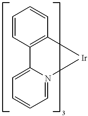
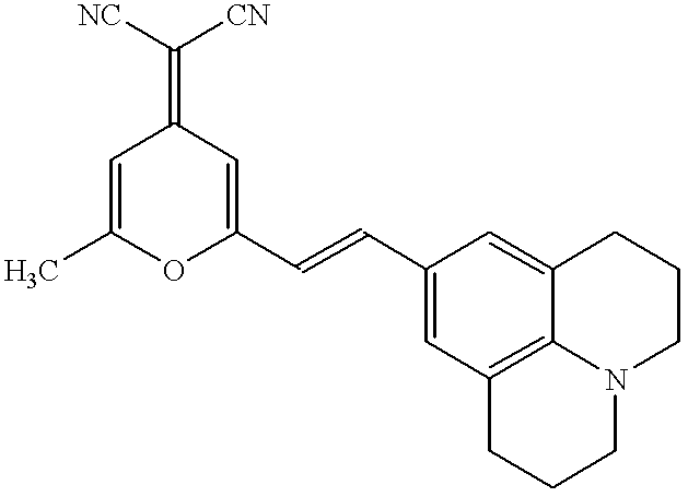
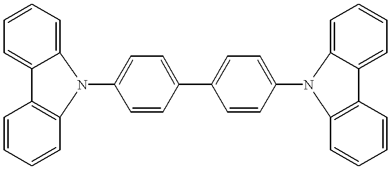
[0089] Organic layers were deposited by a high vacuum (10.sup.-6 Torr) thermal evaporation onto a clean glass substrate pre-coated with a 1400.ANG.-thick layer of transparent and conductive indium tin oxide. A 600.ANG.-thick layer of N,N'-diphenyl -N,N'-bis (3-methylphenyl)-[1,1'-bi-phenyl]-4,4'diamine ["TPD"] is used to transport holes to the luminescent layer. The luminescent layer consisted of an alternating series of 10.ANG.-thick layers of CBP doped to 10% (by mass) of Ir(ppy).sub.3, and 10.ANG. thick layers of CBP doped to 1% (by mass) of DCM2 . In total, 10 doped layers were grown with a total thickness of 100.ANG.. Excitons were confined within the luminescent region by a 200.ANG.-thick layer of the exciton-blocking material 2.9-dimethyl-4,7-diphenyl-1,10-phenanthroline (also called bathcuproine, or BCP). A 300.ANG.-thick layer of the electron transport material tris-(8-hydroxyquinoline) aluminum ("Alq.sub.3") is used to transport electrons to the luminescent region and to r...

second embodiment

[0098] V.B.1. Overview of Second Embodiment

[0099] The second embodiment is directed to the situation wherein the emissive molecule is phosphorescent and the use of intersystem crossing molecules enhances the efficiency of the phosphorescent emission.

[0100] V.B.2. Example of Second Embodiment

##ic example 4

Prophetic Example 4

[0101] An OLED is fabricated with a traditional diamine hole transporter and an electron transporting layer (ETL) composed of three different materials. The ETL is roughly 80% a traditional electron transporting material (such as Zrq4), 15% an intersystem crossing agent (such as benzil; other ISC agents may be found in the reference of Gilbert and Baggott) and 5% a phosphorescent emitter (such as PtOEP, platinum octaethyl porphyrin). The ISC agent is chosen so that its absorption spectrum overlaps strongly with the ETL's fluorescence spectrum. Hole electron recombination occurs at or near the HTL / ETL interface generating a mixture of singlet and triplet excitons. The singlet excitons on the ETL will efficiently transfer their energy to the ISC agent, which will efficiently intersystem cross to its triplet state, via a .fwdarw..pi.* state or some other suitable process.

[0102] The triplet energy of the ISC agent will then transfer to the dopant and emission will occ...


PUM

PropertyMeasurementUnit
transparencyaaaaaaaaaa
diffusion lengthsaaaaaaaaaa

Abstract

Organic light emitting devices are described wherein the emissive layer comprises a host material containing a fluorescent or phosphorescent emissive molecule, which molecule is adapted to luminesce when a voltage is applied across the heterostructure, wherein an intersystem crossing molecule of optical absorption spectrum matched to the emission spectrum of the emissive molecule enhances emission efficiency.

Description

I. FIELD OF INVENTION[0001] The present invention is directed to organic light emitting devices (OLEDs) comprised of emissive layers that contain an organic compound functioning as an emitter and a separate intersystem crossing ("ISC") entity which operates to enhance the efficiency of the emission.II. BACKGROUND OF THE INVENTION[0002] II. A. General Background[0003] Organic light emitting devices (OLEDs) are comprised of several organic layers in which one of the layers is comprised of an organic material that can be made to electroluminesce by applying a voltage across the device, C. W. Tang et al., Appl. Phys. Lett. 1987, 51, 913. Certain OLEDs have been shown to have sufficient brightness, range of color and operating lifetimes for use as a practical alternative technology to LCD-based full color flat-panel displays (S. R. Forrest, P. E. Burrows and M. E. Thompson, Laser Focus World, Feb. 1995). Since many of the thin organic films used in such devices are transparent in the vis...

Claims


Application Information

Patent Timeline
Patent Type & Authority Applications(United States)
IPC IPC(8): C09K11/06H01L51/00H01L51/30H01L51/50
CPCH01L51/0059H01L51/0062H01L51/0081H01L51/0084H01L51/0085H01L2251/308H01L51/5012H01L51/5016H01L51/5028H01L51/5096H01L51/0088H10K85/631H10K85/649H10K85/324H10K85/341H10K85/342H10K85/348H10K50/11H10K2101/10H10K50/121H10K50/18H10K2102/103H05B33/14
Inventor FORREST, STEPHEN R.THOMPSON, MARK E.BALDO, MARC A.
Owner THE TRUSTEES FOR PRINCETON UNIV
Why Eureka
Try Eureka