

Electric DC-cable with an insulation system
- Summary
- Abstract
- Description
- Claims
- Application Information
AI Technical Summary
Benefits of technology
Problems solved by technology
Method used
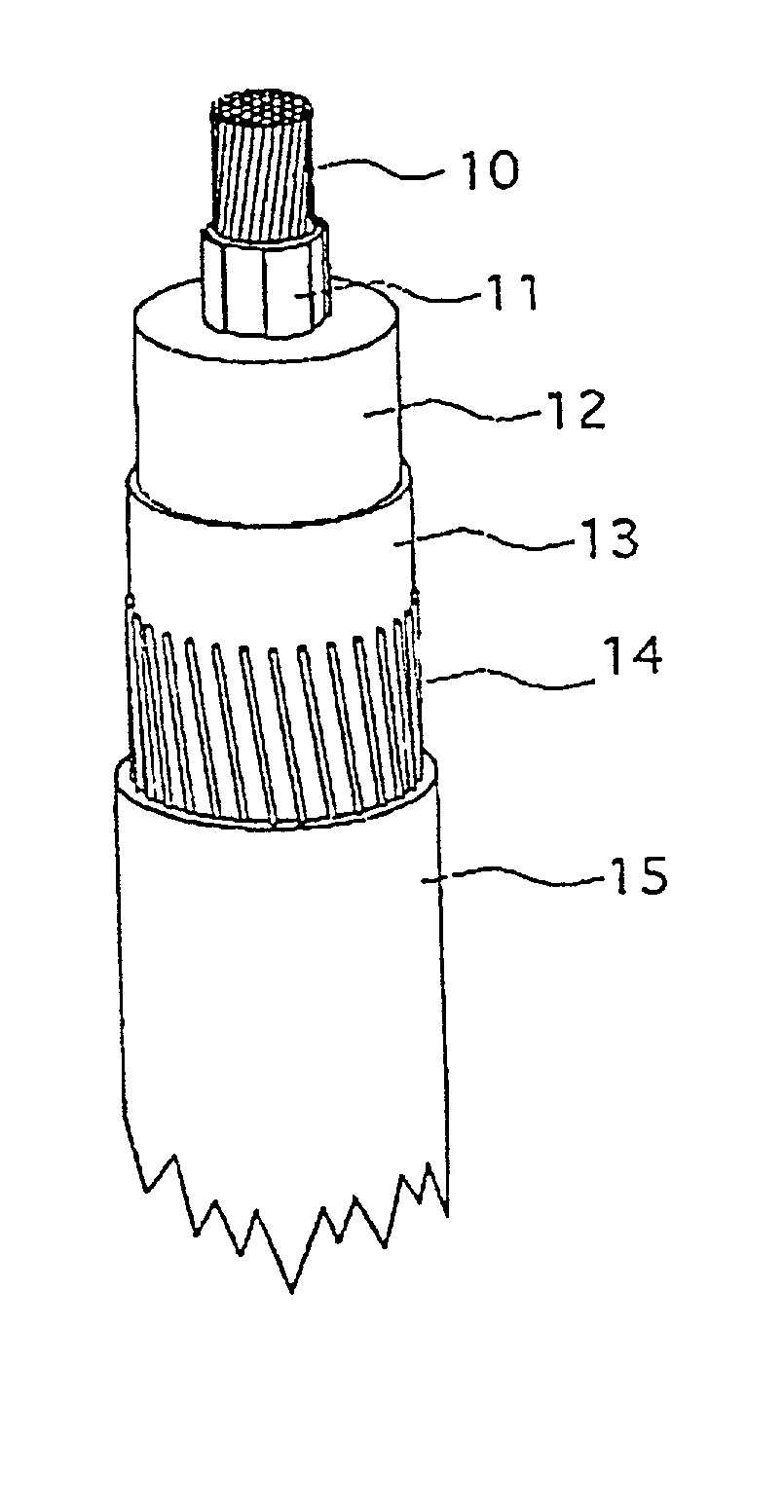
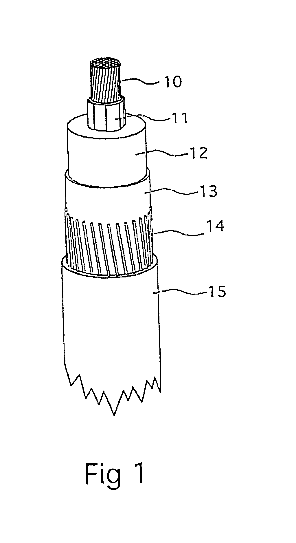
Image

Examples
example 1
[0066] Comparative Tests
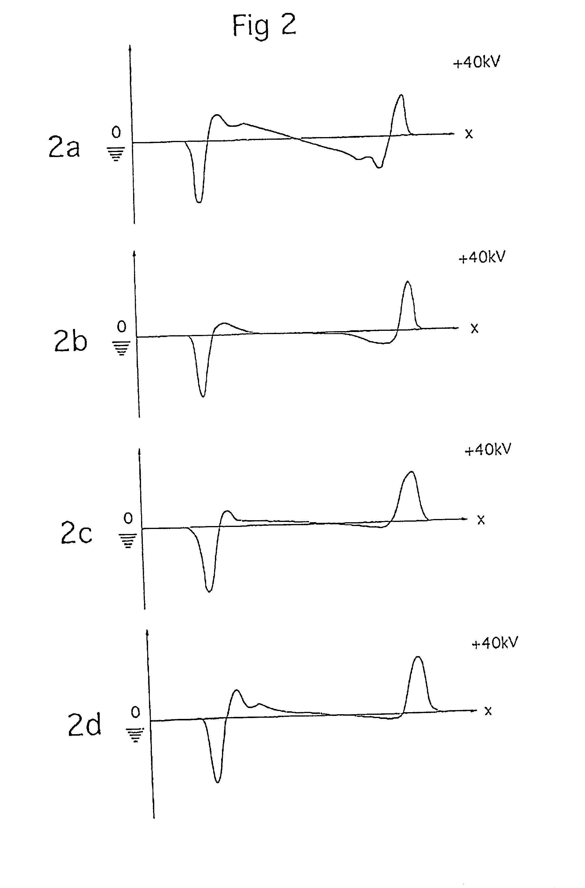
[0067] Test plates with compositions as used in prior art insulated AC-cables and in accordance with the present invention for use in insulated DC-cables were produced, processed and subjected to an evaluation of the tendency for space charge accumulation by recording space charge profiles using the Pulsed ElectroAccoustic (PEA) technique. The PEA technique is well known within the art and described by Takada et al. in IEEE Trans. Electr. Insul. Vol. EI-22(No.4). pp 497-501(1987).
[0068] a,A 2 mm thick test plate of a polyethylene composition comprising:
[0069] about 98% by weight of low density polyethylene (922 kg / m.sup.3) of melt flow rate 0.8 g / 10 min.
[0070] about 0,4% by weight of an antioxidant SANTONOX R.RTM. (Flexsys Co) with the chemical designation 4,4'-thio-bis-(6-tert-butyl-m-cresol), and about 1,6% by weight of a cross linking agent, DICUP R.RTM. (Hercules Chem) with the chemical designation dicumyl peroxide, was molded at 130.degree. C.
[0071] Two ...
example 2
[0092] a polyethylene based resin composition was compounded as described in the following. to a low density polyethylene resin with a MFR of 1.2 g / 10 min following additions were made,
[0093] a peroxide cross-linking agent in the form of dicumyl peroxide was added in an amount of 1.7% by weight,
[0094] a scorch retarding agent in the form of compound (D), 2,4-diphenyl-4-methyl-pentene-1, was added in an amount of 0.3% by weight, and an antioxidant system consisting of
[0095] compound (B) in the form of DSTDP, di-stearyl-thio-dipropianate and
[0096] compound (C), a diester of 3-(3,5-di-tert-butyl-4-hydroxyphenyl) propionicacid and thiodiglycol, was added to the polyethylene resin in a total amount of 0.3% by weight. The ratio of compound B to compound C was 1:3. The compounded resin composition was extruded to a 8 mm insulation on a shielded, stranded multi-wire conductor and cross-linked at a product temperature of 225.degree. C. and for a limited processing time of 5 minutes.
[0097] No...
example 3
[0100] A polyethylene based resin composition was compounded as described in the following. To a low density polyethylene resin with a MFR of 1 g / 10 min the following additions were made,
[0101] a peroxide cross-linking agent in the form of dicumyl peroxide was added in an amount of 1.4% by weight,
[0102] a scorch retarding agent in the form of compound (D), 2,4-diphenyl-4-methyl-pentene-1, was added in an amount of 0.4% by weight, and an antioxidant system consisting of compound (C), a diester of 3-(3,5-di-tert-butyl-4-hydroxyphenyl) propionicacid and thiodiglycol, only was added to the polyethylene resin in an amount of 0.3% by weight. The compounded resin composition was extruded and cross-linked at a temperature of 300.degree. C.
[0103] The tendency for space charge accumulation was, when tested, low and substantially reduced in relation to the space charge accumulation normally detected in conventional extruded cross-linked polyethylene based compositions as used for AC-cables. Th...
PUM
| Property | Measurement | Unit |
|---|---|---|
| Fraction | aaaaa | aaaaa |
| Percent by mass | aaaaa | aaaaa |
| Percent by mass | aaaaa | aaaaa |
Abstract
Description
Claims
Application Information