Fiber reinforced plastic pipe and power transmission shaft employing the same

a technology of fiber reinforced plastic pipe and power transmission shaft, which is applied in the direction of pipes, mechanical equipment, transportation and packaging, etc., can solve the problems of destroying the effectiveness of the aforementioned various techniques, difficult to provide an elongated shaft, and complex assembly

Active Publication Date: 2002-08-29
NTN CORP +2
View PDF21 Cites 24 Cited by
  • Summary
  • Abstract
  • Description
  • Claims
  • Application Information

AI Technical Summary

Benefits of technology

[0016] 1. According to a first aspect of the present invention, an FRP pipe reduced in thickness and increased in diameter by pultrusion process, comprises a fiber bundle spun and aligned in the longitudinal direction, and circumferential reinforced fiber sheet provided at least either on an outer surface layer or on an inner surface layer. In this invention, the fiber bundle is spun and aligned in the longitudinal direction of the pipe, thereby allowing for making full use of the mechanical properties of the fibers for use with the FRP pipe. The FRP pipe is also provided with the circumferential reinforced fiber sheet at least on either the outer surface layer or the inner surface layer of the FRP pipe, thereby making it possible to prevent tensile strain from developing in the circumferential direction of the pipe. Consequently, this makes the pipe robust against the crushing force exerted from the circumference and less prone to longitudinal cracks or other cracks.
[0017] 2. According to a second aspect of the present invention, an FRP pipe reduced in thickness and increased in diameter by pultrusion process, comprises a fiber bundle spun and aligned in the longitudinal direction, and circumferential reinforced fiber sheet provided at least either on an outer surface layer or on an inner surface layer, and has a slit, capable of being reduced in diameter along the circumference, provided in the longitudinal direction. In this arrangement, the fiber reinforced plastic pipe can be inserted into a metal pipe. In this invention, upon incorporating the FRP pipe into the metal pipe, reducing the FRP pipe in diameter in the circumferential direction makes it possible to elastically deform the pipe by the width of the slit. This makes the assembly considerably easier in comparison with a case where a cylindrical pipe with no slit is press-fitted into the metal pipe. Consequently, it is possible to provide an FRP pipe which enables to make full use of its practical performance without damaging the FRP pipe.
[0018] 3. According to a third aspect of the present invention, in a power transmission shaft comprising a metal joint element and a metal pipe jointed to each other, an FRP pipe is inserted into the metal pipe, the FRP pipe being reduced in thickness and increased in diameter by pultrusion process, comprising a fiber bundle spun and aligned in the longitudinal direction, and circumferential reinforced fiber sheet provided at least either on an outer surface layer or on an inner surface layer. In this invention, the FRP pipe having a high flexural rigidity is disposed inside the metal pipe, thereby making it possible to improve the flexural rigidity of the power transmission shaft. This allows for eliminating a support bearing at the intermediate portion or a dynamic damper for preventing vibrations, thereby reducing the shaft in weight and cost and providing an elongated shaft.

Problems solved by technology

Accordingly, improvements have been required for the shaft in weight and cost, and thus it has been difficult to provide an elongated shaft.
However, in a case where the FRP pipe and the metal pipe are formed in the shape of a simple cylinder and have a tolerance of size, respectively, it is necessary to match the dimensions with each other to control subtle press-fitting or press-fit pressures in the process, thereby making the assembly extremely complicated.
However, in a case where upon inserting the FRP pipe into the metal pipe, the FRP pipe is so damaged due to cracks as not to make use of its practical performance, the effectiveness of the aforementioned various techniques is ruined, making it difficult to employ the FRP pipe for use with the power transmission shaft.
However, an FRP pipe which is reduced in thickness and increased in diameter by pultrusion process makes such a problem noticeable that the FRP pipe is sensitive to crushing force exerted from the circumference, thereby causing longitudinal or other cracks to readily develop.
This tensile stress increases in proportion to the width of the slit of the FRP pipe, thereby increasing the possibility of occurrence of cracks.
In particular, reinforcement fibers spun being aligned in the longitudinal direction of the pipe may easily raise the problem that longitudinal or other cracks are also caused by the stress developed due to thermal expansion in addition to the stress caused by an external force.
On the contrary, a slit width W greater than 40% of the outer circumference of the FRP pipe may increase the amount of imbalance in rotation, thereby causing a problem of runouts at high speed rotations.
Accordingly, this would make it difficult to improve the flexural rigidity of the power transmission shaft that has incorporated an FRP pipe of fibers having a high elasticity.
This is because a molded product having layers of more than twenty would make the preparation work considerably complicated, thereby compromising its mass productivity.
For fibers of diameter less than 1 .mu.m, acrylic fibers employed as raw material are costly.
In addition to this, it is difficult to control the process of forming carbon fibers by carbonization.
This in turn increases the cost of the fibers, thus making it difficult to provide shafts at low cost.
For fibers of diameter larger than 20 .mu.m, it is difficult to provide fibers having a high elasticity.
Accordingly, it is difficult to increase the first-order flexural resonance frequency of the power transmission shaft.
However, the filament winding employed together with the pultrusion process would require a special apparatus and thus affect productivity.
For the power transmission shaft of a vehicle in which the ambient temperature is on the order of 60.degree. C., an epoxy resin having a resistance to heat of less than 60.degree. C. after having been cured may cause a serious problem, and thereby cannot be used as the matrix.
For a metal pipe 11 greater than 6000 mm in length, it is difficult to install the pipe in a vehicle even when the vehicle is a truck.
That is, this makes it impossible to employ a metal-to-metal joint method appropriately at least on one side of the resulting power transmission shaft.
This also makes it difficult to design the inner diameter and thickness of the metal pipe 11 to satisfy only the static torsional strength required of the power transmission shaft for use with a vehicle.
A metal pipe 11 of thickness more than 10 mm is too heavy to be employed as the shaft for use with a passenger car, thus making it impossible to achieve the object of reducing weight.
On the other hand, a metal pipe 11 of outer diameter greater than 250 mm would raise a space problem that the pipe interferes with other parts inside the vehicle.
However, this would cause the relative amount of FRP being used to increase, thereby raising a problem of increasing manufacturing costs.

Method used


Image

  • Fiber reinforced plastic pipe and power transmission shaft employing the same
  • Fiber reinforced plastic pipe and power transmission shaft employing the same
  • Fiber reinforced plastic pipe and power transmission shaft employing the same

Examples


Embodiment Construction

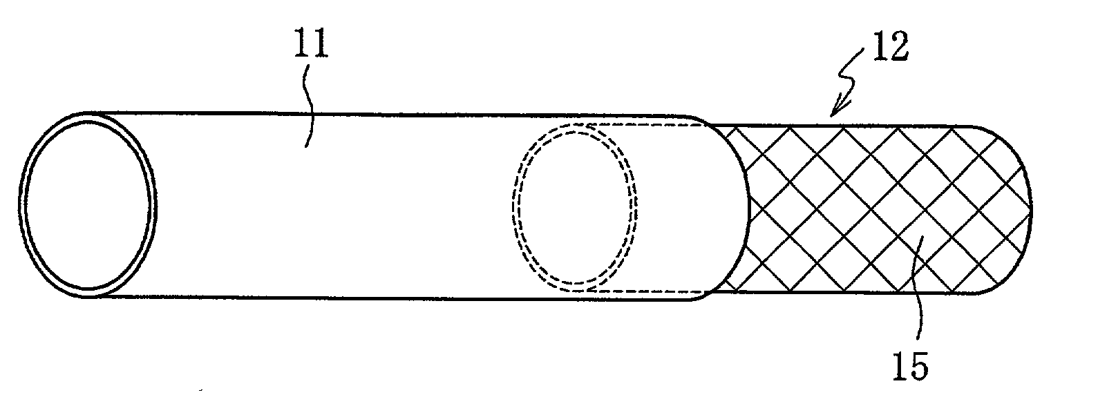
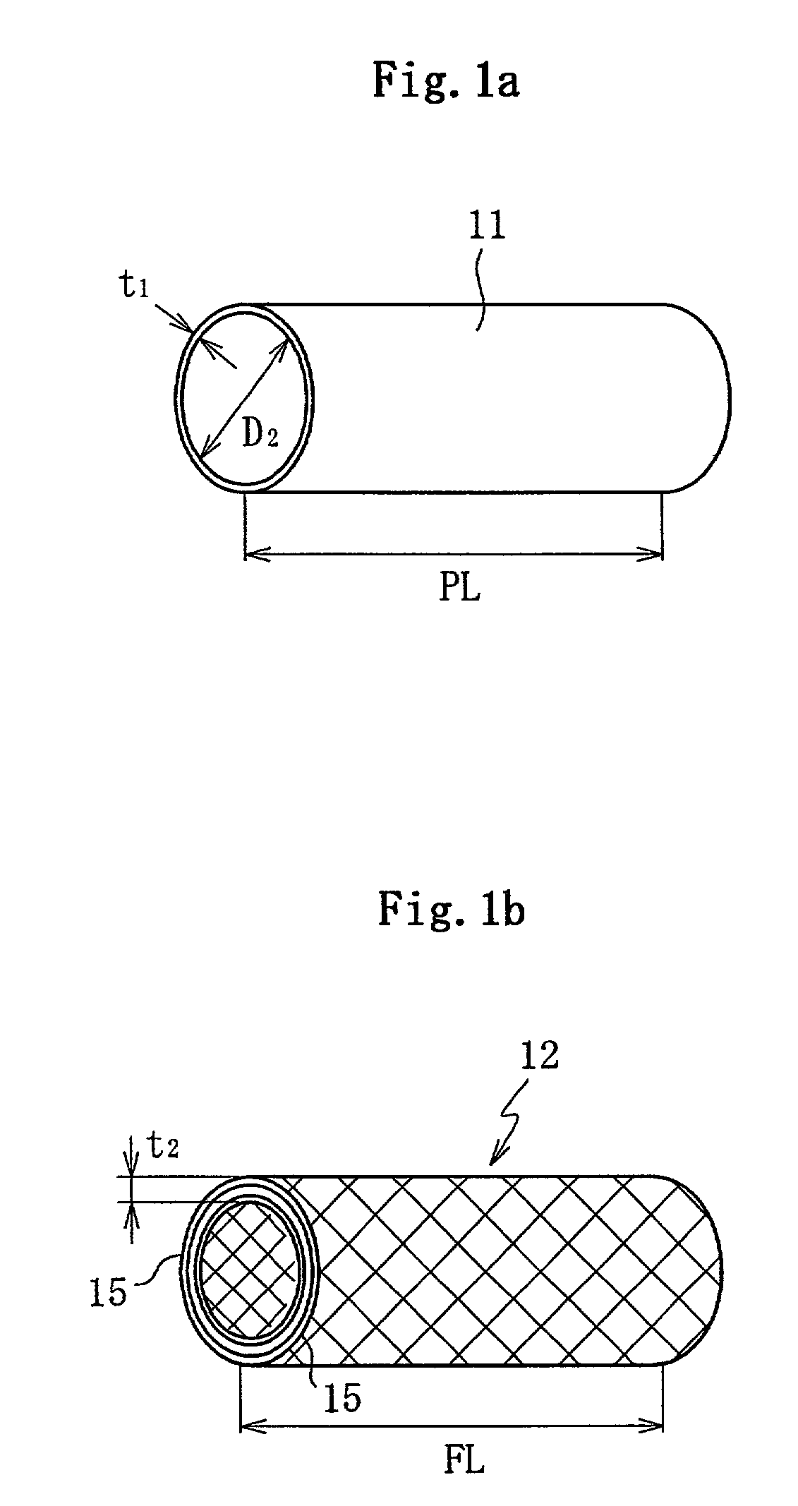
, the pultrusion process was used to form an FRP pipe (70 mm in outer diameter and 3 mm in thickness) while the tow of PAN-based carbon fibers of elasticity 255 kN / mm.sup.2, "PYROFIL TRH50 made by Mitsubishi Rayon Co., Ltd.," and a continuous strand mat employing glass fibers of elasticity 72.3 kN / mm.sup.2, "CSM#300 made by Asahi Fiber Glass Co.," were being impregnated with a vinyl ester resin, "8250H made by Japan U-Pica Co., Ltd."

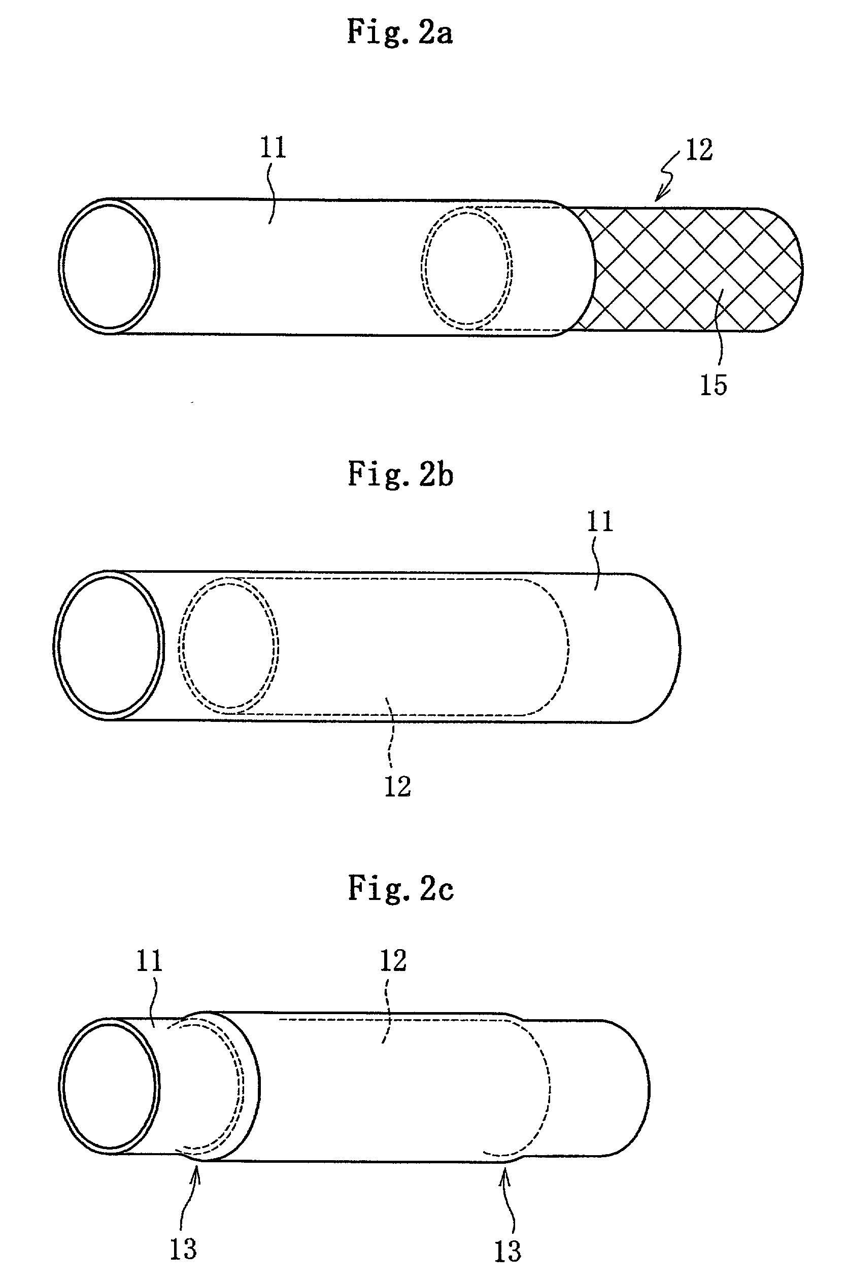
[0086] The glass fiber sheet 15 was arranged on the outer and inner surface layers of the FRP pipe 12, while carbon fibers were spun and aligned in the axial direction. A slit of 0.8 m in length and 9 mm in width was provided on the FRP pipe, which was then elastically deformed in the circumferential direction. Then, the FRP pipe was inserted into a steel pipe (of STKM13B, 70 mm in outer diameter, 1.4 mm in thickness, and 0.9 m in length) down to the middle portion. Then, the FRP pipe with the slit was allowed to expand in the circumferential direction t...


PUM

PropertyMeasurementUnit
thicknessaaaaaaaaaa
anglesaaaaaaaaaa
bias angleaaaaaaaaaa

Abstract

A fiber reinforced plastic pipe is provided to prevent it from being damaged and make full use of its practical performance when the fiber reinforced plastic pipe, reduced in thickness and increased in diameter by pultrusion process, is reduced in the circumferential direction and inserted into a metal pipe. The fiber reinforced plastic pipe, reduced in thickness and increased in diameter by pultrusion process, includes a fiber bundle spun and aligned in the longitudinal direction, and circumferential reinforced fiber sheet provided at least on one of the outer and inner surface layers. The circumferential reinforced fiber sheet is inserted into the metal pipe to form a power transmission shaft such as an intermediate shaft for use with a propeller shaft or a drive shaft.

Description

[0001] 1. Field of the Invention[0002] The present invention relates to a fiber reinforced plastic pipe for use such as with a propeller shaft or a drive shaft which constitutes part of the power transmission system of a vehicle. The present invention also relates to a power transmission shaft incorporating the fiber reinforced plastic pipe.[0003] 2. Description of the Related Art[0004] Those shafts that constitute the power transmission system of a vehicle include a propeller shaft for transmitting power from the gearbox to the reduction gear, and a drive shaft for coupling the engine and the hub joint. Any of the shafts is provided at the ends thereof with universal joints, and constructed to respond to variations in length and angle resulting from changes in relative position between the gearbox and the reduction gear or between the engine and the hub joint.[0005] FIG. 8 is a view illustrating an example of a power transmission shaft, showing the overall view of a propeller shaft...

Claims


Application Information

Patent Timeline
Patent Type & Authority Applications(United States)
IPC IPC(8): B60K17/22B29C70/52F16C3/02
CPCF16C3/026F16C2326/06
Inventor NAKAJIMA, TATSUOMATSUI, ARITONISHIMOTO, TAKASHIITOHIYA, GOASAI, HAJIMETAKANO, TSUNEO
Owner NTN CORP
Why Eureka
Try Eureka