Electrochemical cell with a non-liquid electrolyte

Inactive Publication Date: 2002-09-05
FLEISCHER NILES A +4
View PDF0 Cites 108 Cited by
  • Summary
  • Abstract
  • Description
  • Claims
  • Application Information

AI Technical Summary

Problems solved by technology

Reducing the thickness of a rechargeable battery results in very thin electrodes.
However, some of these batteries employ electrodes composed of metals, such as palladium (see for example U.S. Pat. No. 4,894,301), which are expensive, or materials which may be dangerous to health and difficult to manufacture.
Since these compounds are reduced irreversibly under these conditions, they are not suitable for rechargeable batteries.
In addition, these compounds suffer from one or more of the following deficiencies: low cell voltages, toxicity, significant solubility in the electrolyte, instability with regards to the electrolyte, poor shelf-life, high self-discharge, and low power density.
Besides the disadvantages mentioned above for the aromatic nitro compounds, the halogenated compounds also suffer from being corrosive, producing chlorine odors and are difficult to handle.
However inherent deficiencies limit their applicability in practical batteries.
These electrode materials are not stable with respect to the liquid electrolyte and so they degrade.
In addition, these electrode materials are soluble in liquid electrolytes and so the integrity of the electrodes is significantly diminished and ther

Method used


Image

  • Electrochemical cell with a non-liquid electrolyte
  • Electrochemical cell with a non-liquid electrolyte

Examples


example 2

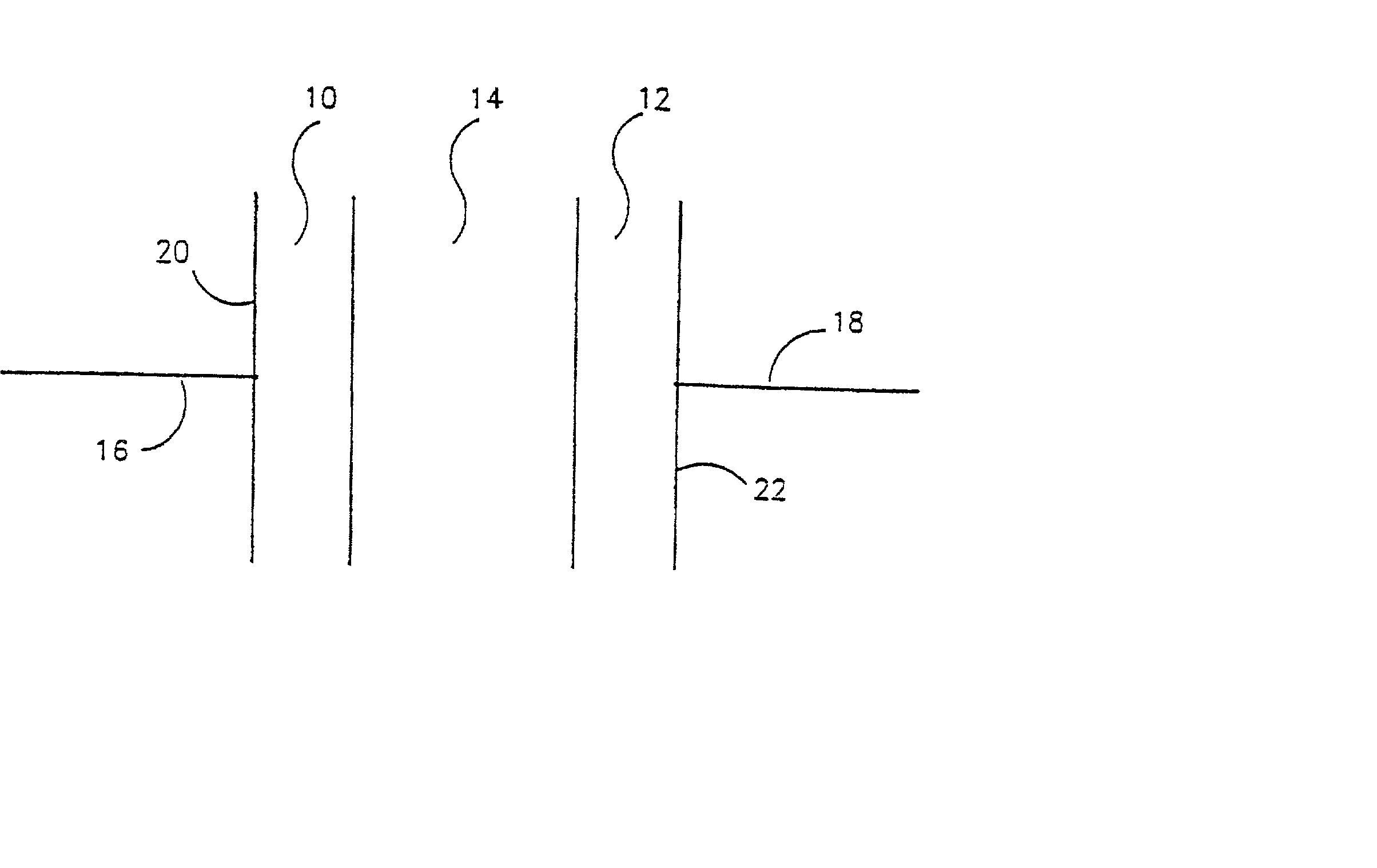
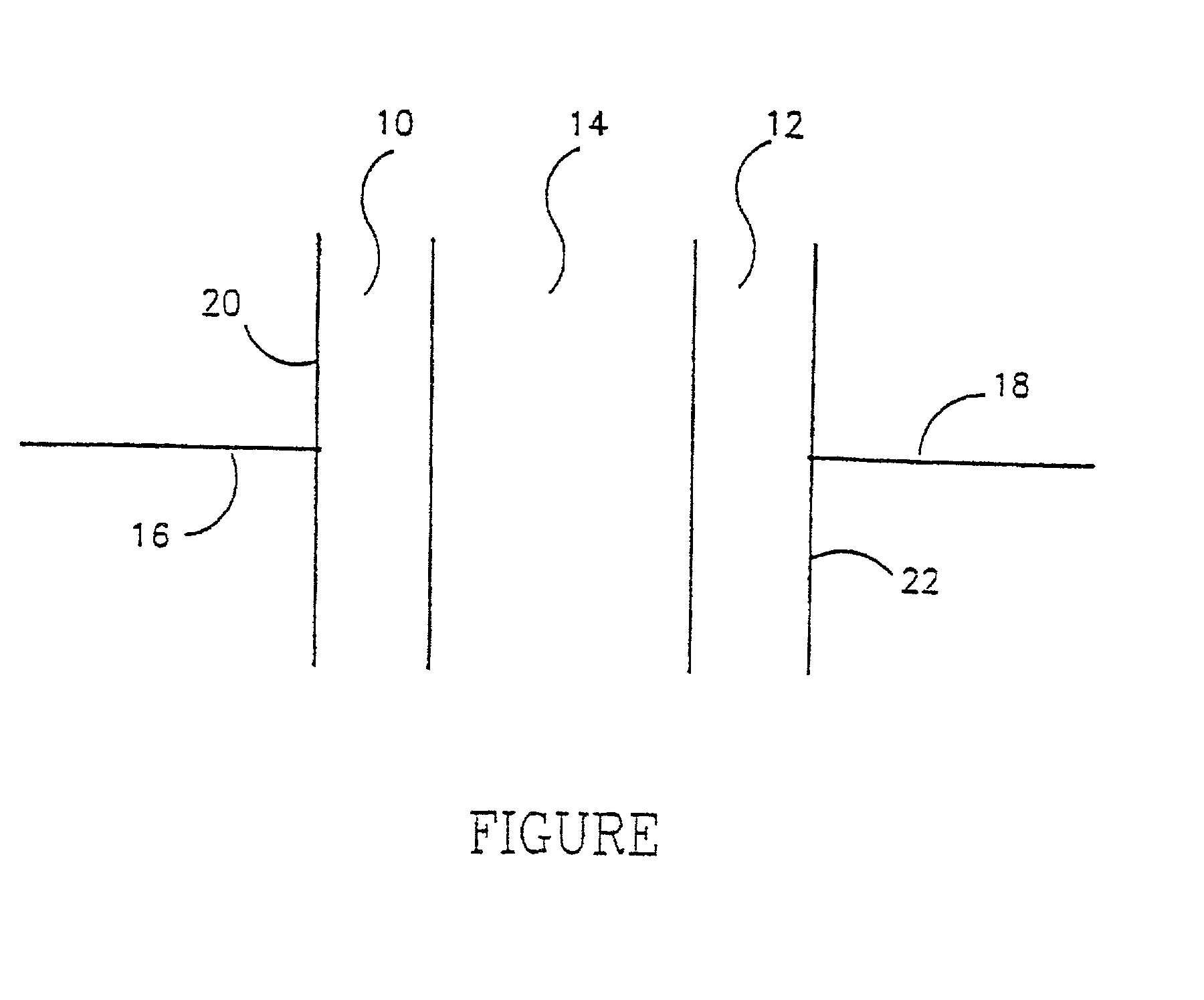
[0130] A three cell bipolar battery was constructed using the same procedure as in Example 1. The anode mix (A-2-M) consisted of 350 mg A-1 mixed with 150 mg of MPA. Thus, the A-2-M mix contained by weight 56% HQ, 14% graphite and 30% MPA.

[0131] The cathode mix (C-2-M) consisted of 350 mg of C-1 mixed with 150 mg of MPA. Thus the C-2-N mix consisted by weight of 63% MnO.sub.2, 7% graphite and 30% MPA. The order of the construction was the same as in Example 1. After the graphite sheet had been placed on top of the C-2-M mix, the order was repeated twice more in order to build a three cell battery in the plastic die. The graphite sheets between the cells acted as a bipolar current collector.

[0132] The open circuit voltage of the battery was +1.66 volts, or +0.553 volts per cell. This battery was discharged and charged as in Example 1.

example 3

[0133] This example illustrates how anodes can be prepared as inks and then painted onto the solid electrolyte. Poly-vinyl alcohol was dissolve in an aqueous solution, carbon powder was added, and the mixture was blended by high speed stirring. Then chloranilic acid was added to this mixture and blended in by further high speed stirring.

[0134] The ink thus prepared was painted onto the solid electrolyte and allowed to air dry. The cathode ink from Example 4 below was painted onto the other side of the solid electrolyte and allowed to dry.

[0135] The resulting cell cycled a number of times showing representative battery action. For one ordinarily skilled in the art it is clear that one can also paint the electrodes onto the cell current collectors and then sandwich the solid electrolyte between them in order to form a battery cell.

example 4

[0136] This example illustrates how cathodes can be prepared as inks and then painted onto the solid electrolyte. Poly-vinyl alcohol was dissolve in an aqueous solution, carbon powder was added to the solution and the mixture was blended by high speed stirring. Then manganese sulphate was added to this mixture and blended in by further high speed stirring. For use of this ink for construction of a battery please refer to Example 3 above.


PUM


Abstract

A non-liquid electrolyte containing electrochemical cell which operates efficiently at room temperature. The cell includes: (a) a non-liquid electrolyte (14) in which protons are mobile; (b) an anode (10) including an active material based on the organic compound which is a source of protons during cell discharge; and (c) a solid cathode (12) including a compound which forms an electrochemical couple with the anode. The active materials can be chosen so that the cell has the feature that the electrochemical reactions at the anode and cathode are at least partially reversible. An important feature of the cell is that no thermal activation is required for its operation. Therefore, the cell efficiently operates under ambient temperatures.

Description

FIELD AND BACKGROUND OF THE INVENTION[0001] This invention relates to electrochemical cells which can be used as power sources for storage and release of electrical energy. In particular, this invention relates to electrochemical cells such as, but not limited to, batteries, capacitors and hybrid electrochemical cells termed batcaps. The latter exhibit characteristics of both a battery and a capacitor. More particularly, this invention relates to electrochemical cells which accomplish the conversion of chemical energy to electrical energy at ambient temperature by using a non-liquid electrolyte in which protons are mobile, which cells require no thermal activation for their operation.[0002] Electrochemical cells including batteries, capacitors and batcaps are useful for storage and / or release of electrical energy and use similar electrolytes and electrodes. They differ, however, in the mechanisms used for energy storage and energy almost entirely via reversible charge transfer react...

Claims


Application Information

Patent Timeline
IPC IPC(8): H01M4/38H01M4/48H01M4/58H01M4/60H01M10/36
CPCH01M4/383H01M4/48H01M4/5825H01M4/60H01M10/0562H01M10/36H01M2300/0005H01M2300/0082H01M4/38Y02E60/10
Inventor FLEISCHER, NILES A.MANSSEN, JOOSTLANG, JOELCHODESH, ELI ROSHANTELMAN, MARVID
Owner FLEISCHER NILES A
Why Eureka
Try Eureka