
Method, apparatus and flow cell for high sensitivity detection of fluorescent molecules

a fluorescent molecule and high-sensitivity detection technology, applied in the field of optical methods for high-sensitivity detection of fluorescent molecules, can solve the problems of difficult detection of adequately, inability to amplification the molecules to be detected, and limited diffusion of known methods

Inactive Publication Date: 2002-09-12
CELLECTRICON
View PDF0 Cites 8 Cited by
  • Summary
  • Abstract
  • Description
  • Claims
  • Application Information

AI Technical Summary

Benefits of technology

[0012] The object of the present invention is to provide a simple method and apparatus that enables high-sensitivity detection of fluorescent molecules, and in particular ultra-sensitivity detection of single fluorescent molecules in a flowing stream, said detection having a sampling efficiency close to unity. This means that it will be possible to detect a single molecule present in a solution regardless of the volume of the solution.
[0024] It is possible to use more than one light source, and it is then advantageously if each light source emits light at a different wavelength. This enables simultaneous detection of molecules with different fluorescence spectral properties.
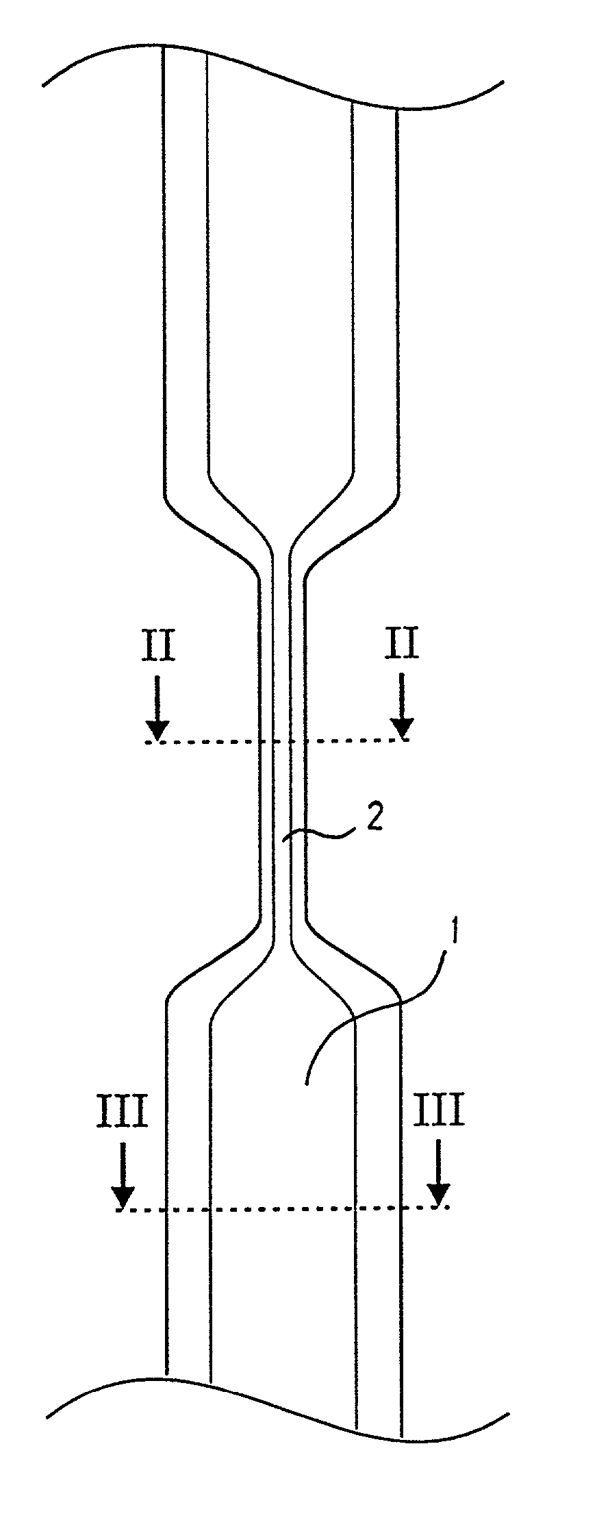
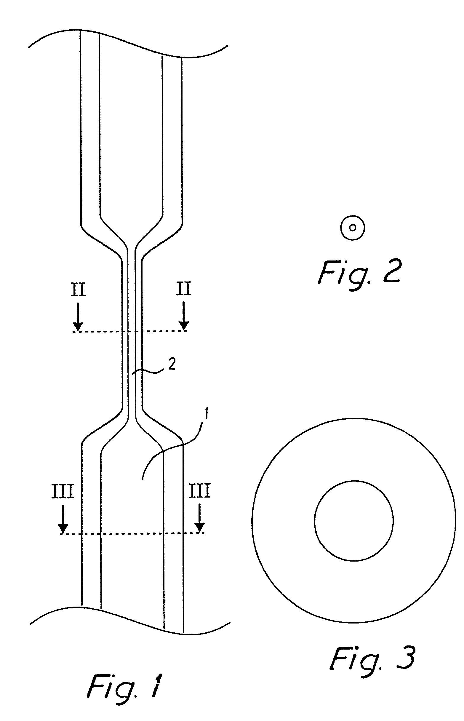
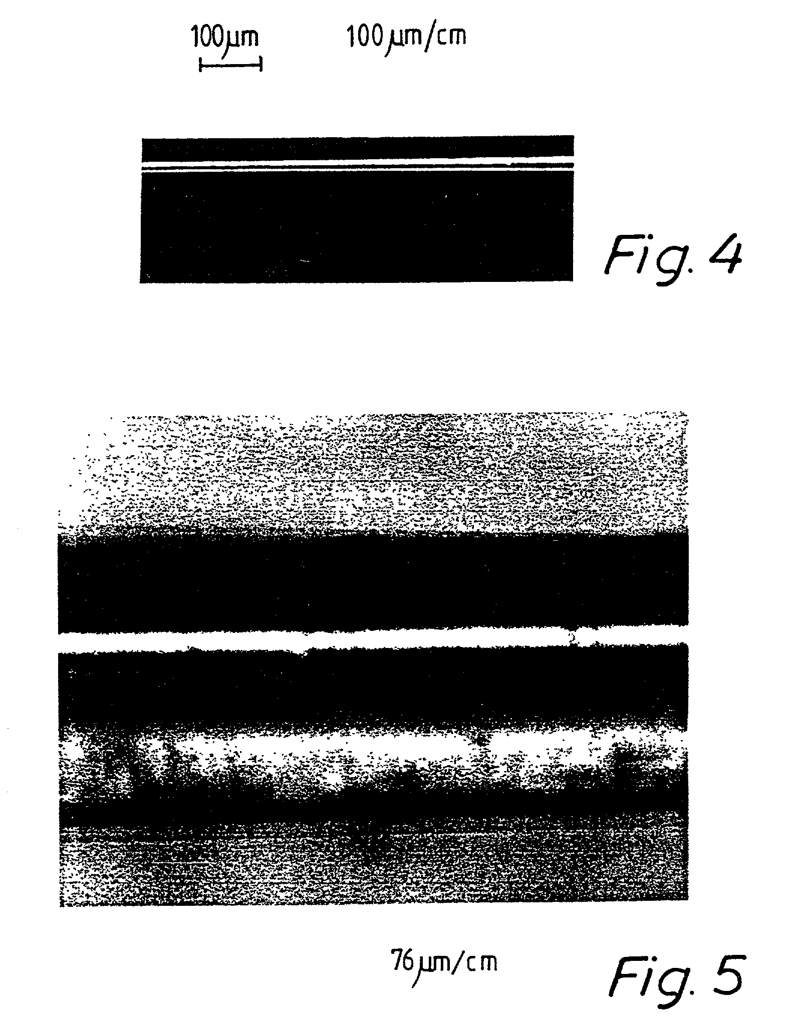
[0029] The dimensions of the constricted region of the flow cell according to the invention is made to match the size of the volume being illuminated by the light. The constricted region preferably has an inner diameter (i.d.) of approximately 0.2-8 .mu.m, and an outer diameter (o.d.) of approximately 0.4-40 .mu.m. Since the constricted region of the flow cell is physically narrower than the rest of the flow cell, the solution travelling through the flow cell is focused in the constricted region. Since only a small portion of the flow cell is constricted, the flow cell can accommodate large sample volumes. This possibility to handle large sample volumes is an important and distinctive feature of the present invention. The concentration sensitivity is several orders of magnitude higher than previous accounts of single molecule detection. It is possible to detect a single molecule almost independent of the sample volume in e.g. a flow injection analysis scheme. Since many biological samples are concentration limited rather than volume limited, this aspect of the invention is important. Once the sample is introduced in the flow cell, the probability of detecting the molecules is almost unity since the dimensions of the probe volume and the constricted region are well matched, and all molecules will traverse the probe volume. With knowledge of the total sample volume injected into the flow cell, this can yield sample concentration without calibration. This is also an important and distinctive feature of the present invention because it abolishes the need to detect analytes in standard solutions of known concentrations. Hence, quantitative analyses can be performed at lower cost and higher sample turnover rate than conventional technologies.
[0030] In order to maintain the quality of the light beam and to minimise spherical and other aberrations, the channel walls are made extremely thin, on the order of a few microns or less. These thin walls minimise the cylindrical lensing effects observed for capillaries with walls of regular thicknesses.
[0031] It is advantageously to place the constricted region in a medium with a refractive index close to that of the material constituting said constricted region. This medium is preferably oil or water, or water supplemented with appropriate additives. This results in a higher optical tuning of the system, by avoiding the light passing through a medium with a refractive index of 1.
[0032] Furthermore, it is advantageously that the channel structure comprises more than one constricted region. It is then possible to measure the emitted fluorescence at different constricted regions and cross-correlate the data in order to improve the probability of identifying a true detection event from a chaotic background event.

Problems solved by technology

However, these samples often contain very small amounts of the molecules in question and they are therefore difficult to detect adequately.
However, amplification of the molecules to be detected is not always desirable since it may, for example, lead to the introduction of substances contaminating the sample.
However, the known methods are diffusion-limited and can be employed only for samples containing a large amount of fluorescent molecules.
With this technique it is, however, difficult to accomplish detection of molecules separated by a microchemical fractionation technique.
However, also according to this technique, high concentrations of the molecules to be detected are necessary.
The sample containing the molecules to be detected is placed in a chamber or on a coverslip and detection of a single molecule is therefore diffusion limited.
However, the instrumentation and analysis (deconvolution algorithms) have been difficult to implement in some cases and most of the techniques does not have the desired concentration detection limits since the probe volume is much smaller than the dimensions of the capillaries.

Method used


Image

  • Method, apparatus and flow cell for high sensitivity detection of fluorescent molecules
  • Method, apparatus and flow cell for high sensitivity detection of fluorescent molecules
  • Method, apparatus and flow cell for high sensitivity detection of fluorescent molecules

Examples


example 1

Detection of Individual 30-nm Fluorescent Beads in a Pulled Capillary By Scanning Confocal Fluorescence Microscope (SCFM)

[0089] The optical set-up used in this example is the preferred embodiment illustrated in 14, which has been described above. The sample analysed in different ways in this example was a disperse solution of latex beads with a diameter of approximately 30 nm, containing an equivalent of approximately 100 fluorescein molecules (Molecular Probes, Eugene, Oreg., U.S.A). Three experiments were made, wherein detection was performed in three different ways; in a regular capillary, in a pulled capillary with a constricted region according to the invention and in a drop on a coverslip.

experiment 1

[0090] The result of detection of the fluorescent beads in a regular 360 .mu.m-outer-diameter 150 .mu.m-inner-diameter fused silica capillary with a 105 .mu.m wall thickness is shown in FIG. 16. The capillary used in this first experiment did not comprise any constricted regions. The capillary wall therefore dramatically distorts the excitation laser beam, which in turn results in significant distortions of the laser focus. Since the capillary wall has a cylindrical symmetry, it acts as a cylindrical lens that strongly focuses the laser beam along one dimension. This cylindrical distortion is the main cause of the observed spherical aberration in this system. Spherical aberration is detrimental to the performance of a confocal microscope. It is clear from the figure that it is not possible to detect any fluorescence signal from the beads over the background noise in this configuration.

experiment 2

[0091] The result from detection according to the invention is shown in FIG. 17. The detection of the fluorescent beads was performed during a 3 second detection period in a capillary similar to the one used in the first experiment, except for the fact that it comprised a constricted region with an inner diameter of about 8 .mu.m, an outer diameter of about 18 .mu.m, and thus a wall thickness of about 5 .mu.m. This 20-times reduction of wall thickness is crucial to maintaining a good quality laser focus for detection with SCFM. Although the presence of the capillary still introduces spherical aberration, the extent of this aberration is dramatically reduced. At the limit where the dimensions of the pulled capillary is comparable to that of the laser focus (about 1 or 2 .mu.m), spherical aberration introduced by the capillary would become negligible. The signal collected from this constricted region of the capillary demonstrates that individual beads can be detected with good signal...


PUM


Abstract

Method and apparatus for high-sensitivity fluorescence detection wherein (I) a sample comprising fluorescent molecules is made to flow through a channel structure (1) including a constricted region (2) with a dimension corresponding to the size of a tightly focused laser spot and with extremely thin, transparent walls; (II) a laser beam (3) is focused inside the constricted (2) and thus exciting molecules passing through the constricted region (2); and (III) the fluorescence emitted due to excitation is detected. This enables direct determination of the concentration of a sample without use of internal or external standards. A method for the production of a flow cell for use in the method or apparatus, wherein a part of a channel structure (1) is heated until its melting point is reached, followed by pulling of the structure to lengthen the melted region and make it thinner until it has a dimension corresponding to the size of a tightly focused laser spot at the diffraction limit.

Description

TECHNICAL FIELD OF THE INVENTION[0001] The present invention relates to an optical method for high-sensitivity detection of fluorescent molecules based on the use of a highly focused light beam and light-induced fluorescence spectroscopy, to an apparatus for high-sensitivity detection of fluorescent molecules comprising a light source and a fluorescence detector, to a method for the production of a flow cell for high-sensitivity detection of fluorescent molecules, as well as to use of said method, apparatus or flow cell in combination with a microscope.BACKGROUND ART[0002] Techniques based on miniaturised chemical separation have made possible the analysis of the contents of individual cells (O. Orwar, H. A. Fishman, N. Ziv, R. H. Scheller, R. N. Zare, Anal. Chem., 67, 4261 (1995)), and individual subcellular organelles (D. T. Chiu, S. J. Lillard, R. H. Scheller, R. N. Zare, S. E. Rodriguez-Cruz, E. R. Williams, O. Orwar, M. Sandberg, J. A. Lundqvist, Science in press). However, the...

Claims


Application Information

Patent Timeline
IPC IPC(8): G01N21/05G01N21/64
CPCG01N21/05G01N21/645G01N21/6458G01N2021/6482G01N2021/0346
Inventor ERIKSSON, PETERORWAR, OWECHIU, DANIEL T.
Owner CELLECTRICON
Learn More