Transfer-type plasma heating anode

Inactive Publication Date: 2002-09-26
NIPPON STEEL CORP
View PDF0 Cites 7 Cited by
  • Summary
  • Abstract
  • Description
  • Claims
  • Application Information

AI Technical Summary

Benefits of technology

0015] The present invention relates to the shape and material of the anode tip end in a plasma heating anode that allows a burn

Problems solved by technology

One of the problems associated with the direct current anode plasma torch is that its life is short because the anode tip end is damaged.
Finally, the temperature of the anode tip end exceeds the melting point, and there is a possibility that the anode tip end is melted and lost.
The central portion of the anode tip end where the burnout critical heat flux is low therefore tends to be melted and lost.
That i

Method used


Image

  • Transfer-type plasma heating anode
  • Transfer-type plasma heating anode
  • Transfer-type plasma heating anode

Examples


example 2

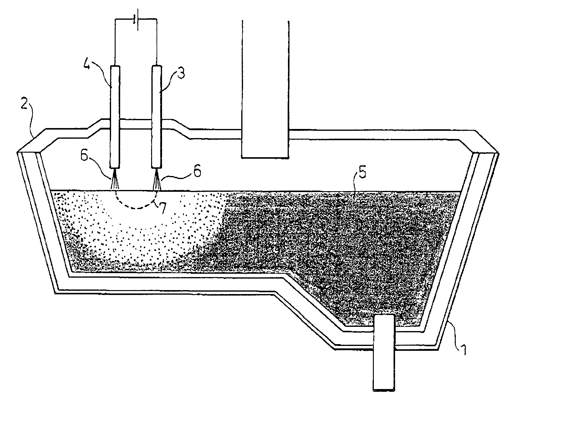
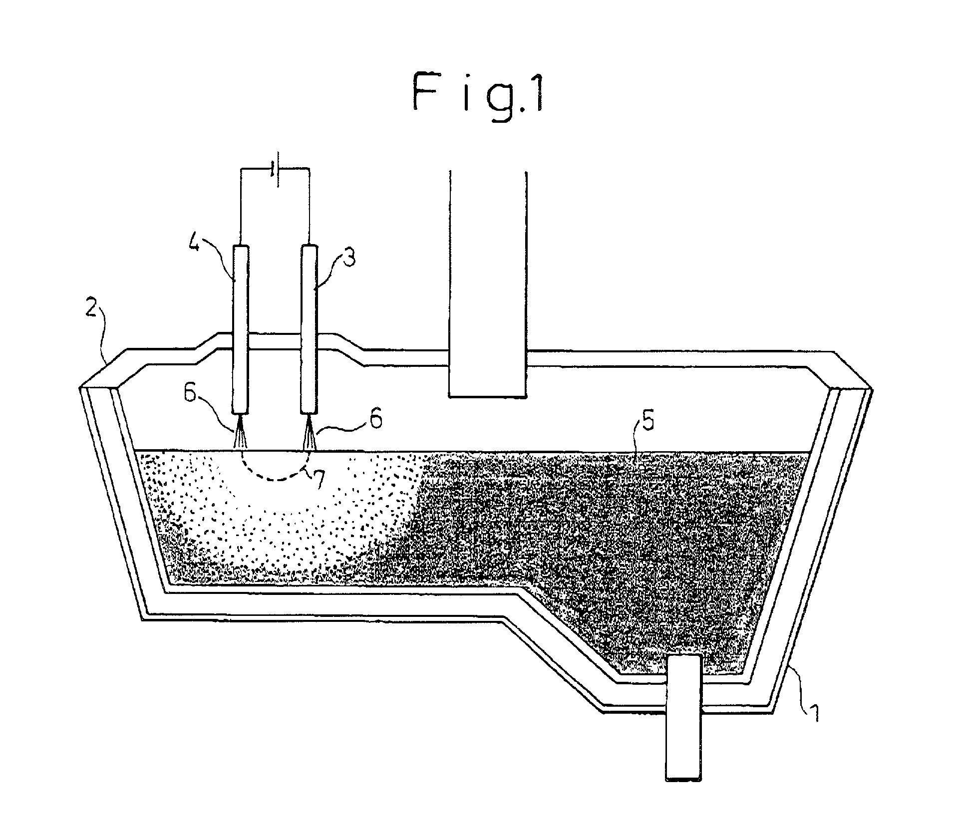
[0096] FIGS. 21, 22, 26 and 27 each show a cross-sectional view of one embodiment of the present invention.

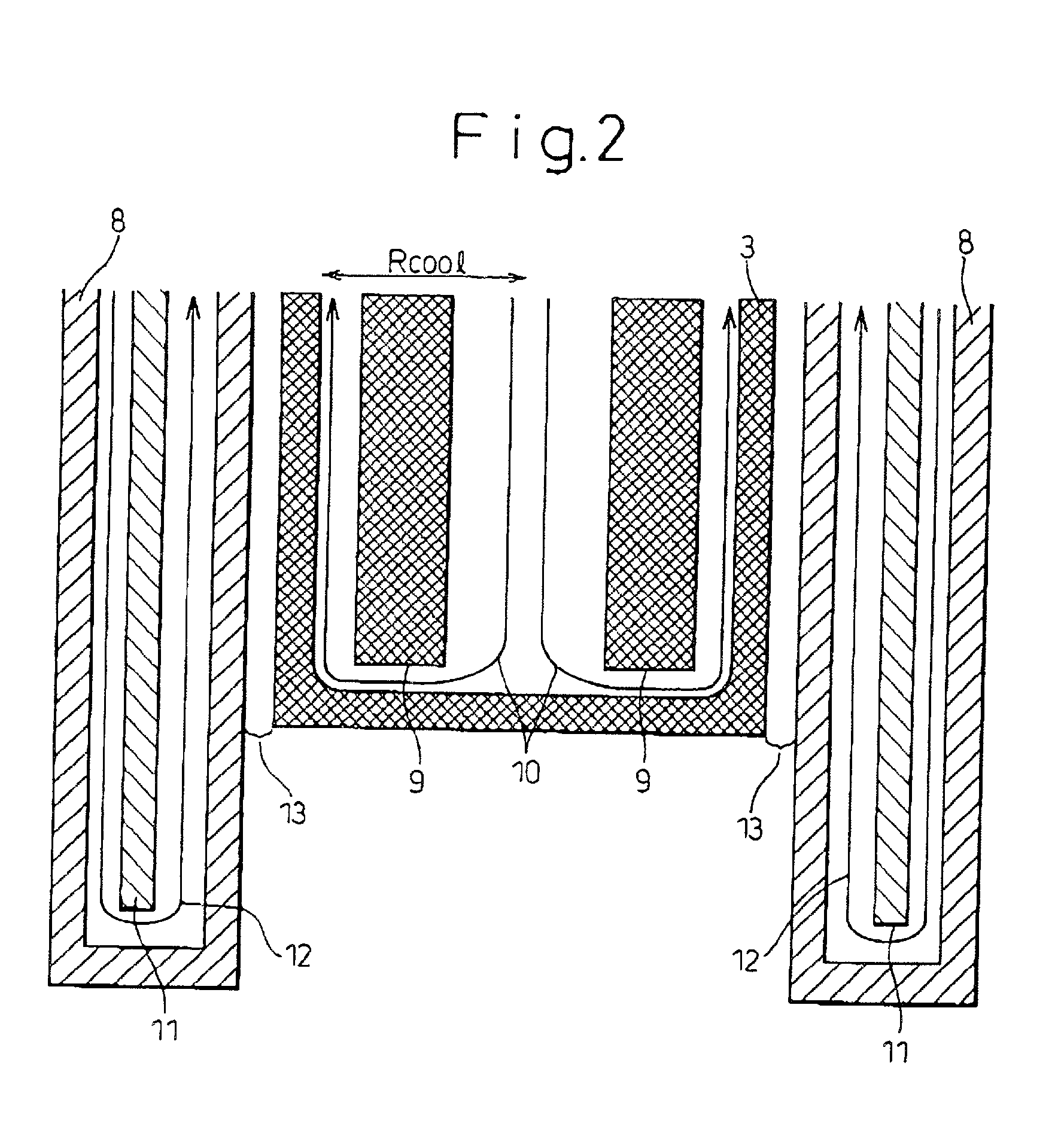
[0097] The features of the anode shown in FIGS. 21 and 26 are explained in the following (1) to (6). In addition, FIG. 21 is a vertical cross-sectional view, and FIG. 26 is a horizontal cross-sectional view.

[0098] (1) The anode tip end has a radius Ra of the external surface of 25 mm, a radius Rcool on the cooling side of 22 mm and a thickness Da of 3 mm.

[0099] (2) A conical projection 51 formed in the center on the cooling side of the anode tip end has a bottom radius Rp of 15 mm and a height Hp of 20 mm. The side face of the conical projection forms is streamlined and matches the flow of cooling water.

[0100] In FIG. 32, a radius on the cooling side of the anode tip end in which the radius Rcool on the cooling side is 22 mm is shown on the abscissa, and a burnout critical heat flux is shown on the ordinate; a change in the heat flux is shown in the figure. In FIG. 32, a dashed...


PUM


Abstract

A transferred plasma heating anode for heating a molten metal in a container by applying Ar plasma generated by passing a direct current through the molten metal, the transferred plasma heating anode comprising; an anode, composed of a conductive metal, that has an internal cooling structure, a metal protector having an internal cooling structure that is placed outside the anode with a constant gap between the anode and the protector, and a gas supply means that supplies an Ar-containing gas to the gap, is characterized by the central portion on the external surface of the anode tip end being inwardly recessed.

Description

[0001] The present invention relates to an improvement in a transferred plasma heating anode and, particularly, to a transferred plasma heating anode suitable for heating a molten steel in a tundish.[0002] FIG. 1 shows a direct current twin-torch plasma heating device used for heating a molten steel in a tundish. Two plasma torches, an anode 3 and a cathode 4, are inserted through a tundish cover 2, and a plasma arc 6 is generated between the torches 3, 4 and a molten steel 5 to heat the molten steel. An electric current 7 flows from the cathode 4 to the anode 3 through the molten steel 5.[0003] One example of an anode plasma torch is shown in FIG. 2. FIG. 2 shows a cross section of the tip end portion of the anode torch. For example, oxygen-free copper is used as a material for the anode 3. The anode torch comprises an outer cylinder nozzle 8 that is made of a stainless steel or copper and that covers the outside and the anode 3 that is made of copper and that is situated inside th...

Claims


Application Information

Patent Timeline
IPC IPC(8): B22D11/11B22D41/015H05B7/00H05B7/18H05H1/28H05H1/34H05H1/40
CPCB22D11/11B22D41/015H05B7/00H05B7/185H05H1/28H05H1/34H05H1/40H05H2001/3421H05H2001/3478H05H1/3421H05H1/3478
Inventor KAWACHI, TAKESHIYAMAMURA, KAZUTOMITAKE, HIROYUKIKINOSHITA, JUNICHIIMANAGA, KATSUHIRODOKI, MASAHIROKIMURA, YOSHIAKIKAWABATA, TERUO
Owner NIPPON STEEL CORP
Why Eureka
Try Eureka