Lithographic projection apparatus, device manufacturing method, and device manufactured thereby

a technology of lithographic projection and manufacturing method, which is applied in the direction of printers, particle charging/ionising stations, geological measurements, etc., can solve the problems of difficult removal or repair, easy damage to the window itself, and build-up of absorbing layers on the surface of optical elements

Inactive Publication Date: 2002-10-24
ASML NETHERLANDS BV
View PDF0 Cites 34 Cited by
  • Summary
  • Abstract
  • Description
  • Claims
  • Application Information

AI Technical Summary

Problems solved by technology

If such particles are allowed to reach the illumination system, which is of course downstream of the radiation source, or further downstream in the apparatus they can damage the delicate reflectors and other elements and cause build-up of absorbing layers on the surfaces of optical elements.
Such damage and built-up layers cause an undesirable loss of beam intensity, increasing necessary exposure times and hence reducing machine through-put, and can be difficult to remove or repair.
However, such a window is itself prone to damage from the contaminant particles and build-up o

Method used


Image

  • Lithographic projection apparatus, device manufacturing method, and device manufactured thereby
  • Lithographic projection apparatus, device manufacturing method, and device manufactured thereby
  • Lithographic projection apparatus, device manufacturing method, and device manufactured thereby

Examples


embodiment 1

[0037] Embodiment 1

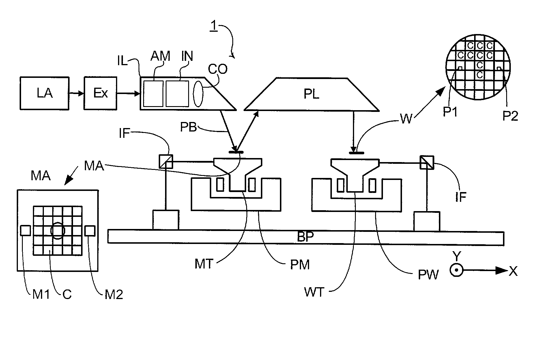
[0038] FIG. 1 schematically depicts a lithographic projection apparatus according to a particular embodiment of the invention. The apparatus comprises:

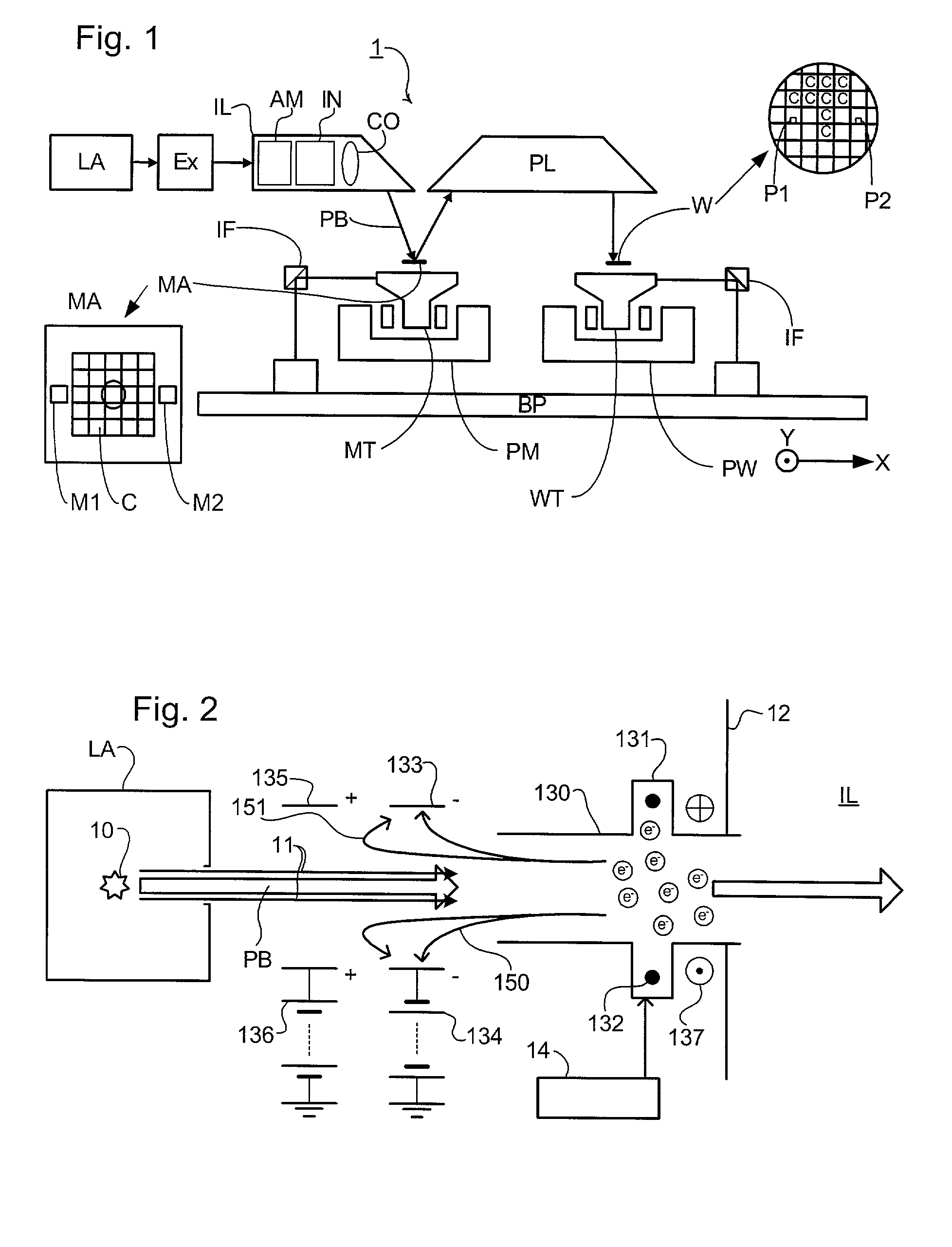
[0039] a radiation system LA, IL, for supplying a projection beam PB of radiation (e.g. EUV radiation), which in this particular case also comprises a radiation source LA;

[0040] a first object table (mask table) MT provided with a mask holder for holding a mask MA (e.g. a reticle), and connected to first positioning means PM for accurately positioning the mask with respect to item PL;

[0041] a second object table (substrate table) WT provided with a substrate holder for holding a substrate W (e.g. a resist-coated silicon wafer), and connected to second positioning means PW for accurately positioning the substrate with respect to item PL;

[0042] a projection system ("lens") PL (e.g. refractive, catadioptric or reflective system) for imaging an irradiated portion of the mask MA onto a target portion C (e.g. comprising o...

embodiment 2

[0058] Embodiment 2

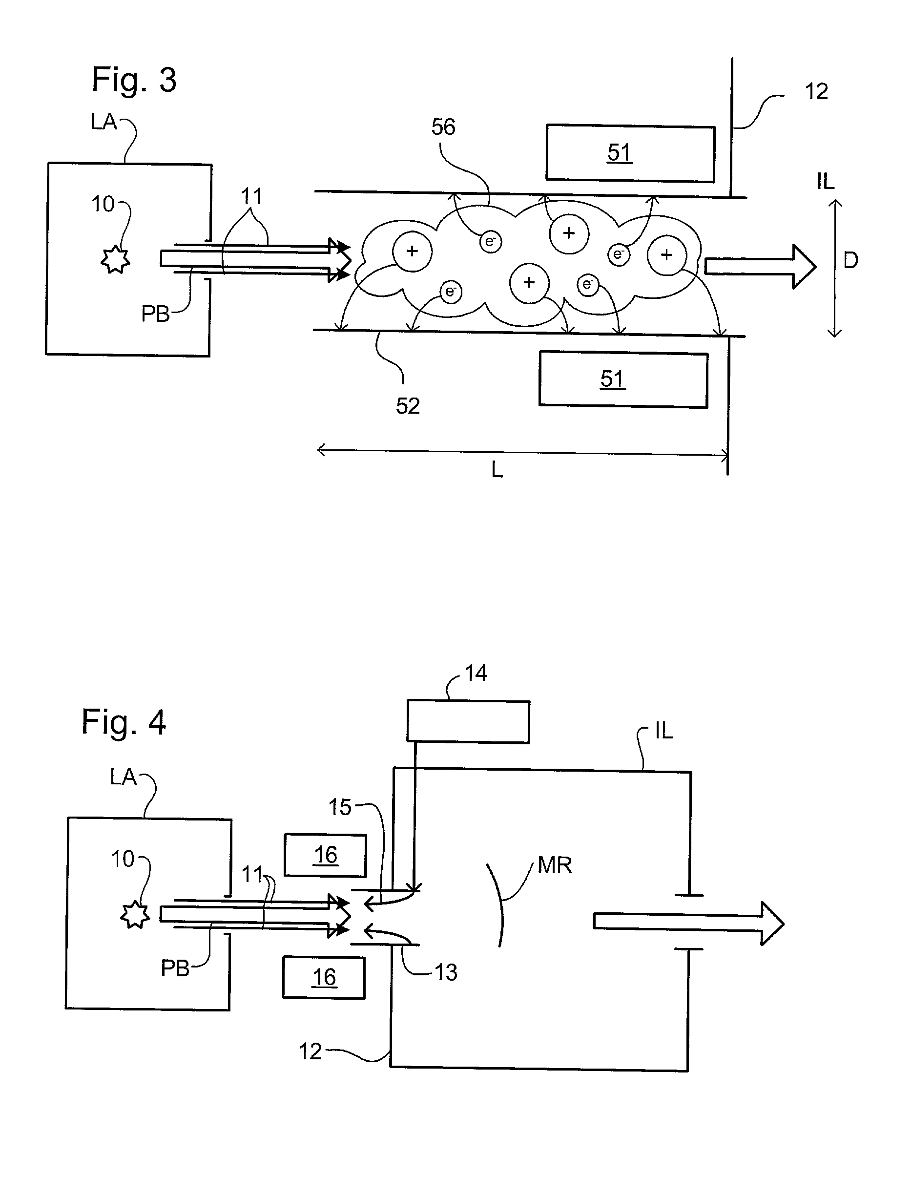
[0059] A second embodiment of the invention is similar to the first embodiment save in that the gas is ionized by generating a plasma and ambipolar diffusion used to remove contaminants. FIG. 3 shows the arrangement for generating the plasma, which replaces the ionization means shown in FIG. 2.

[0060] A plasma 56 of, in this embodiment, noble gases is generated by a plasma generating means 51 which uses, for example, capacitively or inductively coupled RF discharges, or an a / c discharge, for instance, in the frequency range 10 kHz-20 MHz. The electron energy in the plasma 56 should preferably be 10-20 eV or there should be a great concentration of electrons in a high level metastable state. Although other gases can be used in the plasma 56, noble gases are advisable and in particular He and Ar provide for effective ionization.

[0061] As depicted in FIG. 3 the plasma 56 is in a tube 52 having a greater length L than width D. Due to their high temperature the electron...

embodiment 3

[0063] Embodiment 3

[0064] In a third embodiment of the present invention, which may the same as the first or second embodiments of the invention save as described below, a flow of purge gas is provided to impede the contaminant flow towards the illumination system.

[0065] A purge gas supply 14 supplies clean, dry purge gas to outlets (not shown) in the interior wall of the tube 13 to establish a flow 15 of purge gas down the tube toward the radiation source LA. The purge gas may be, for example, a pure inert or noble gas or a mixture of such gases that has a minimum absorption coefficient to the radiation of the projection beam.

[0066] The purge gas flow 15 intercepts and sweeps up the particles of contaminant particle beam 11 and carries them away from the illumination system IL. Exhaust systems 16 are provided either side of the projection beam PB between the radiation source LA and illumination system IL to remove the purge gas flow and entrained contaminant particles. Vacuum pumps...


PUM


Abstract

Contaminant particles travelling with a projection beam in a lithographic projection apparatus are ionized. A purge gas may be attracted towards getter plates provided upstream of the purge gas supply. A magnetic field traps electrons generated by the ionizer to improve the ionization of the purge gas. The contaminant particles can be ionized by generating a plasma in a tube having a greater length than width.

Description

[0001] This application claims priority to EP 01300167.2, herein incorporated by reference in its entirety.[0002] 1. Field of the Invention[0003] The present invention relates generally to lithographic projection apparatus and more particularly to lithographic projection apparatus including a contaminant barrier.[0004] 2. Background of the Related Art[0005] Generally, lithographic projection apparatus in accordance with the present invention include a radiation system for supplying a projection beam of radiation, a support structure for supporting patterning structure, the patterning structure serving to pattern the projection beam according to a desired pattern a substrate table for holding a substrate and a projection system for projecting the patterned beam onto a target portion of the substrate.[0006] The term "patterning structure" as here employed should be broadly interpreted as referring to means that can be used to endow an incoming radiation beam with a patterned cross-sec...

Claims


Application Information

Patent Timeline
IPC IPC(8): B03C3/38H01L21/027H01J27/02H01J37/08G03F7/20
CPCG03F7/70916G03F7/70908G03F7/70933H01L21/027
Inventor KOSTER, NORBERTUS BENEDICTUSMERTENS, BASTIAAN MATTHIASLEENDERS, MARTINUS HENDRIKUS ANTONIUSIVANOV, VLADIMIR VITAL'EVITCHKOSHELEV, KONSTANTIN NIKOLAEVITCHBANINE, VADIM YEVGENYEVICH
Owner ASML NETHERLANDS BV
Why Eureka
Try Eureka