
Electrolyzer for internal combustion engine

a technology of electric motor and internal combustion engine, which is applied in the direction of machines/engines, separation processes, transportation and packaging, etc., can solve the problems of mechanical wear, loss of overall lubricant effectiveness, and further increase of mechanical wear

Inactive Publication Date: 2002-11-14
LYNNTECH POWER SYST
View PDF0 Cites 40 Cited by
  • Summary
  • Abstract
  • Description
  • Claims
  • Application Information

AI Technical Summary

Benefits of technology

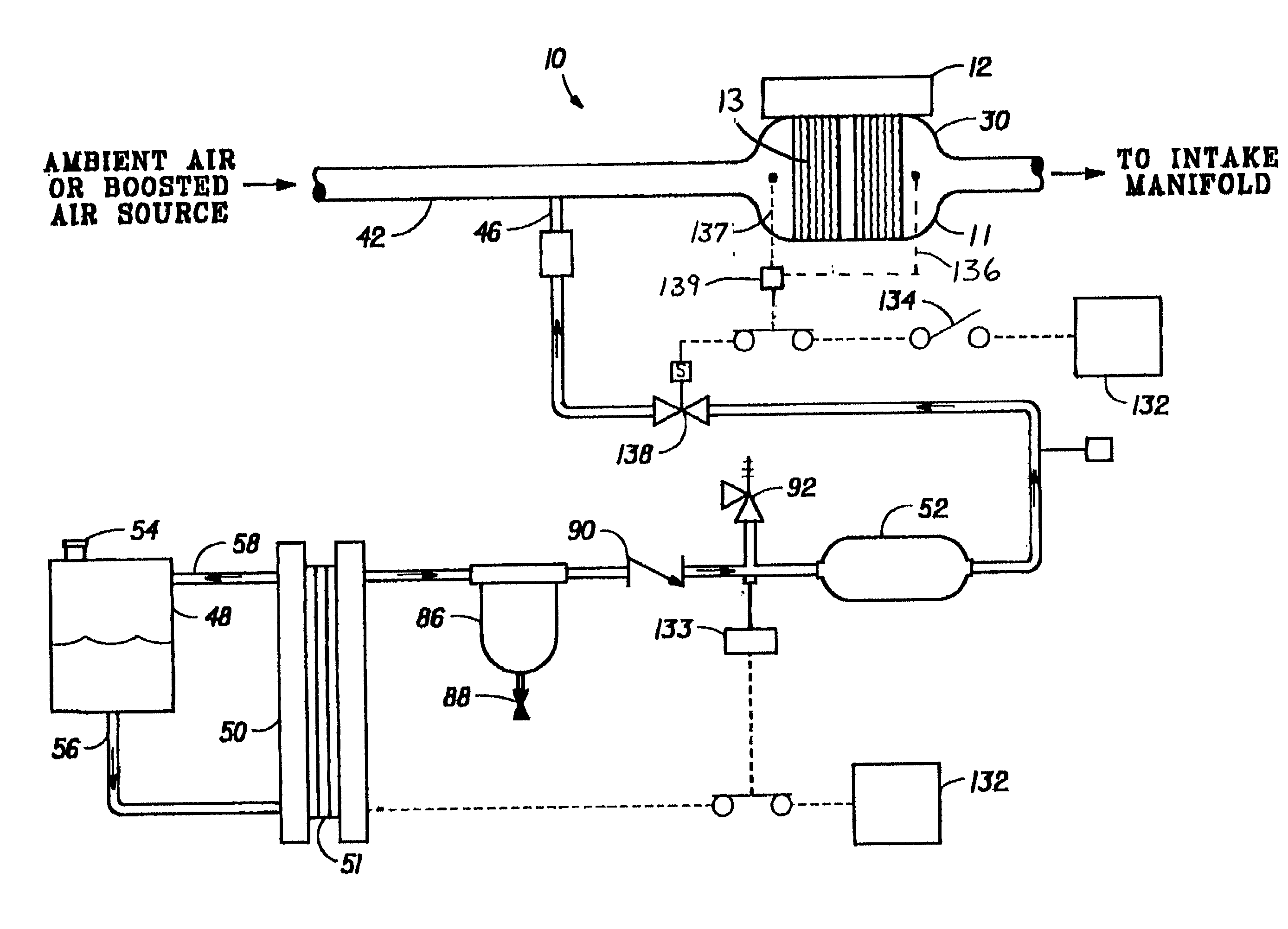
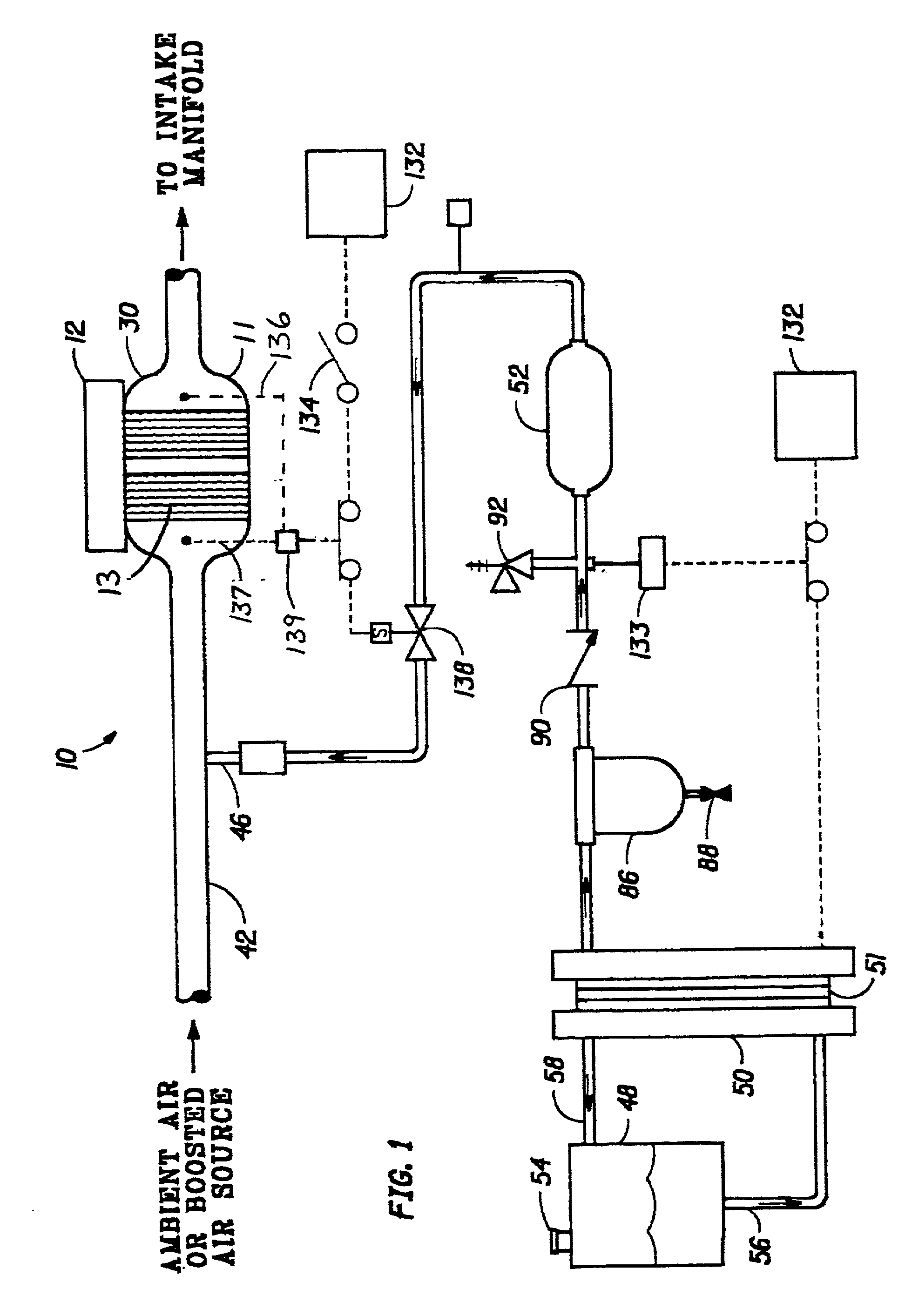
[0013] The present invention provides a method for reducing wear, reducing unwanted emissions and improving operational availability of a combustion engine comprising: disposing a hydrogen oxidation catalyst in the air intake line; catalytically combining hydrogen and oxygen on the catalyst to produce heat; and tranferring the heat to the air by contacting the catalyst and by mixing the intake air with the gasses produced by the exothermic oxidation of hydrogen.

Problems solved by technology

There are several problems that must be overcome during the start-up of an internal combustion engine that is cold.
First, atomized or vaporous fuel in the air / fuel mixture introduced into the engine cylinders tends to condense onto the cold engine components, such as cylinder walls and the air intake rail, especially in compression ignition (CI) engines such as diesel engines.
Condensed hydrocarbon fuels on engine cylinder walls may act as solvents that wash away desirable lubricant films resulting in excessive mechanical wear from reciprocating piston rings in sliding contact with the engine cylinder walls.
The condensed mixture of fuel and lubricant is capable of passing the piston rings, entering the crankcase and contaminating the engine's lubrication reservoir resulting in a loss of overall lubricant effectiveness and a further increase in mechanical wear, even during normal operation.
Second, the condensation of atomized or vaporous fuels onto cold engine cylinder walls results in poor engine performance and delayed engine availability during and immediately after cold engine start-up.
Engine availability is diminished during cold engine start-up due to poor lubricant properties at low temperatures, non-uniform fuel distribution and improper air / fuel mixtures.
Third, if the vehicle is equipped with a catalytic converter increased levels of unwanted pollutants are emitted from the tailpipe for a period of about one to three minutes after cold engine start-up because that is the amount of time normally needed for the engine exhaust gases to heat the catalytic converter in the exhaust system to an efficient operating temperature.
The undesirable levels of pollutants released during and immediately after cold engine start-up present a problem of increasing importance.
However, until the catalyst light-off temperature is reached, the engine exhaust gasses pass through the catalytic converter relatively unchanged, and unacceptably high levels of pollutants such as carbon monoxide, hydrocarbons and nitrogen oxides are released into the atmosphere.
A significant part of overall engine wear occurs during and immediately after cold start-ups, especially in diesel engines which are otherwise extremely durable due to the lubricating effect of diesel fuel at normal operating temperatures.
A high percentage of the undesirable emissions or pollutants created by internal combustion engines equipped with catalytic converters occur during cold start-ups.
The problems of cold engine start-up can be addressed by leaving the engine running continuously, but the unwanted result of this method is excessive fuel consumption and related emissions.
Limitations of the equipment, however, affect the suitability of this method.
The primary limitation on electrical preheating is the amount of electrical energy required by the heater.
The typical automotive battery is not a practical source to supply the electrical power needed to preheat an internal combustion engine because the electrical load on the vehicle battery may exceed the rated battery output.
In any event, the repeated electrical demand necessary for engine preheating in cold temperatures will unacceptably shorten the battery life of the typical automotive battery.
First, the initial start-up of the engine to drive the alternator is necessarily done without preheating, resulting in excessive mechanical wear, unwanted pollutants and poor performance.
Second, an alternator-powered electrical resistance heater still requires a substantial increase in battery capacity to cope with the start-up scenario.
In addition, the maximum alternator power output required by the system requires a complicated switching mechanism to shut down the heater once the engine achieves a suitable operating temperature and an increased alternator speed to 2,000 to 4,500 rpm during the heating period.
There will also be an increased up-front automotive cost because the alternator must be oversized for typical automotive electrical power demand in order to support the heater during and after engine start-up.
To date, there has not been an automotive engine heating system which gives almost instantaneous heating of the engine components or intake air without the inherent drawbacks stated above.

Method used


Image

  • Electrolyzer for internal combustion engine
  • Electrolyzer for internal combustion engine
  • Electrolyzer for internal combustion engine

Examples


Embodiment Construction

[0027] The present invention relates to accelerating the operational availability of internal combustion engines, including both compression ignition and spark ignition engines, by shortening the required "warm-up" period between cold start-up and achieving efficient operating temperature. The present invention is also effective for minimizing mechanical wear in internal combustion engines resulting from unwanted condensation of atomized or vaporous fuel on cold cylinder walls during start-up of combustion engines. Furthermore, the present invention provides for improved catalysis for the reduction of emissions during cold start-up of internal combustion engines.

[0028] More particularly, the present invention relates to a method and apparatus for warming internal combustion engine components such as the block, intake air (oxidant) to the engine, fuel to the engine, the engine lubricant, the battery or other devices associates with internal combustion engines using resident or on-boa...


PUM

PropertyMeasurementUnit
molar ratioaaaaaaaaaa
thickaaaaaaaaaa
areaaaaaaaaaaa

Abstract

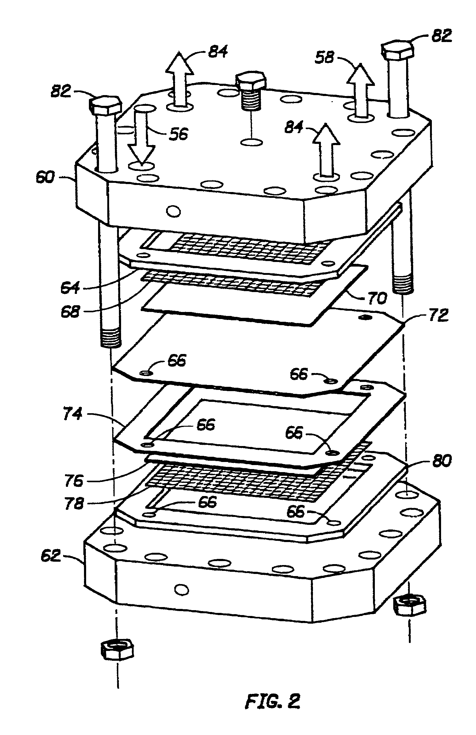
The present invention provides a method and apparatus for chemically heating one or more components of, or intake air flowing to, an internal combustion engine by feeding hydrogen to a catalyst. In accordance with the invention, condensation of fuels on cold engine cylinder walls during and after cold start-ups is prevented, thereby reducing wear on the engine. The invention also provides a method and apparatus for reducing pollutants commonly occurring during cold start-up of combustion engines by heating components of, or intake air flowing to, a combustion engine, in order to quickly warm the engine and its catalytic converter to operating temperatures. Preferably, the hydrogen is supplied from an electrolyzer or other on-board source of hydrogen and the hydrogen and a source of oxygen are provided to the catalyst resulting in exothermic oxidation of hydrogen to heat the air intake or other components of the engine. The invention includes preheating systems for one or more of the air intake, the fuel, the engine oil, the block, the battery and the catalytic converter.

Description

[0001] This application is a divisional application of pending U.S. patent application Ser. No. 09 / 206,828 filed Dec. 7, 1998, which was a continuation-in-part of U.S. patent application Ser. No. 08 / 682,024, filed on Jul. 16, 1996, now U.S. Pat. No. 5,845,4585.[0002] 1. Field of the Invention[0003] The present invention relates to internal combustion engines and methods and apparatus for improving the cold start-up of internal combustion engines.[0004] 2. Background of the Related Art[0005] There are several problems that must be overcome during the start-up of an internal combustion engine that is cold. First, atomized or vaporous fuel in the air / fuel mixture introduced into the engine cylinders tends to condense onto the cold engine components, such as cylinder walls and the air intake rail, especially in compression ignition (CI) engines such as diesel engines. Condensed hydrocarbon fuels on engine cylinder walls may act as solvents that wash away desirable lubricant films result...

Claims


Application Information

Patent Timeline
Patent Type & Authority Applications(United States)
IPC IPC(8): B01D53/94B60H1/00B60H1/18C25B1/10C25B9/20F01N3/20F01N3/28F01N3/32F01N3/34F01N5/02F02B43/10
CPCB01D53/9454Y02T10/24B60H1/18B60H1/2203C25B1/10C25B9/20F01N3/2006F01N3/206F01N3/2889F01N3/32F01N3/34F01N5/02F01N2240/02F01N2610/04F01N2610/08F01P2060/00F01P2060/18F02B43/10F02B2043/106Y02E60/366Y02T10/16Y02T10/26Y02T10/32Y10S123/12Y02T10/22B60H1/00271Y02A50/20Y02E60/36Y02T10/12Y02T10/30C25B1/04C25B9/73
Inventor ANDREWS, CRAIG C.MURPHY, OLIVER J.
Owner LYNNTECH POWER SYST
Learn More