
Film coated optical lithography elements and method of making

a technology of optical lithography and film coating, which is applied in the direction of instruments, photomechanical equipment, sensing by electromagnetic radiation, etc., can solve the problems of economic manufacturability of optical coating, troublesome oxide optical films with tolerable transmission, and hinder commercial use and adoption of such shorter wavelengths in the manufacture of semiconductor integrated circuits

Inactive Publication Date: 2003-01-30
CORNING INC
View PDF11 Cites 34 Cited by
  • Summary
  • Abstract
  • Description
  • Claims
  • Application Information

AI Technical Summary

Problems solved by technology

Commercial use and adoption of such shorter wavelengths in the manufacture of semiconductor integrated circuits has been hindered by the transmission nature of such vacuum ultraviolet wavelengths region through optical materials.
Such slow progression by the semiconductor industry of the use of VUV light below 240 mm such as 193 nm or 157 nm light has been also due to the lack of economically manufacturable optical coatings, optical elements with optical film coatings and optical film precursor materials.
At 193 nm such oxide optical films that may have tolerable transmission are troubled by the formation of high fluence laser radiation exposure defects such as color center formations when exposed to the powerful and damaging 193 nm optical lithography radiation.
At 157 nm such oxide optical materials do not have sufficient transparency for use as thin film optical layers, which limits 157 nm optical films to fluoride crystal materials such as MgF.sub.2, AlF.sub.3, GdF.sub.3 and LaF.sub.3.
Such fluoride crystallite film voids are troublesome contamination sites which are prone to attracting contaminating vapors such as water which can strongly absorb below 185 nm wavelengths.
Attempts to increase crystalline sizes and minimize such voids such as by using energetic ion assisted deposition lead to absorbing film layers owing to the low energy of disassociation of such fluoride crystal materials.
Options for increasing the packing densities of such fluoride crystal films such as by heating the optical surface substrate to about 300.degree. C. elevated temperatures is troublesome and particularly ill advised for high thermal expansion substrate materials such as CaF.sub.2.

Method used


Image

  • Film coated optical lithography elements and method of making
  • Film coated optical lithography elements and method of making
  • Film coated optical lithography elements and method of making

Examples


Embodiment Construction

[0071] The silicon oxyfluoride glass of the invention preferably has very low levels of OH (<10 ppm wt. OH), very low trace levels of metal contaminants (<1 ppm wt.), low levels of molecular hydrogen (H.sub.2<5.times.10.sup.+16 molecules / cm.sup.3) and low levels of chlorine (Cl<10 ppm), and has a F wt. % content of 0.5-3 wt. %, so the glass is preferably provided by forming a soot which is then treated and consolidated to form the silicon oxyfluoride glass which can be further physically treated such as by crushing prior to coating formation.

[0072] The silicon oxyfluoride glass has a beneficial transmission of light in the below 193 nm vacuum ultraviolet lithography region centered around 157 nm.

[0073] The preferred approach for consolidating a soot preform into a silicon oxyfluoride glass includes drying the porous SiO.sub.2 particles in a He / Cl.sub.2 atmosphere between 1000-1100.degree. C. The particles are then heated in a helium fluorine doping atmosphere which includes a fluori...


PUM

PropertyMeasurementUnit
light wavelengthsaaaaaaaaaa
transmission cut off wavelengthaaaaaaaaaa
wavelength rangeaaaaaaaaaa

Abstract

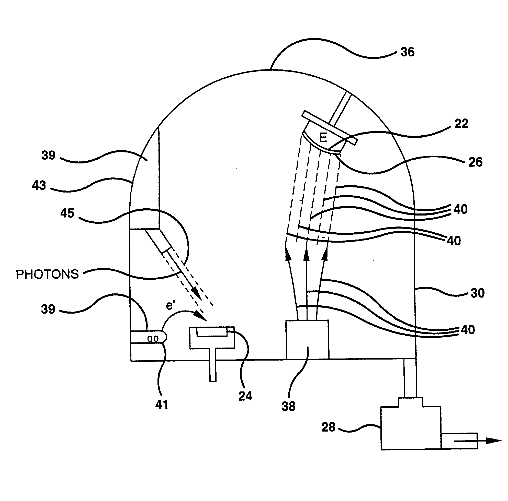
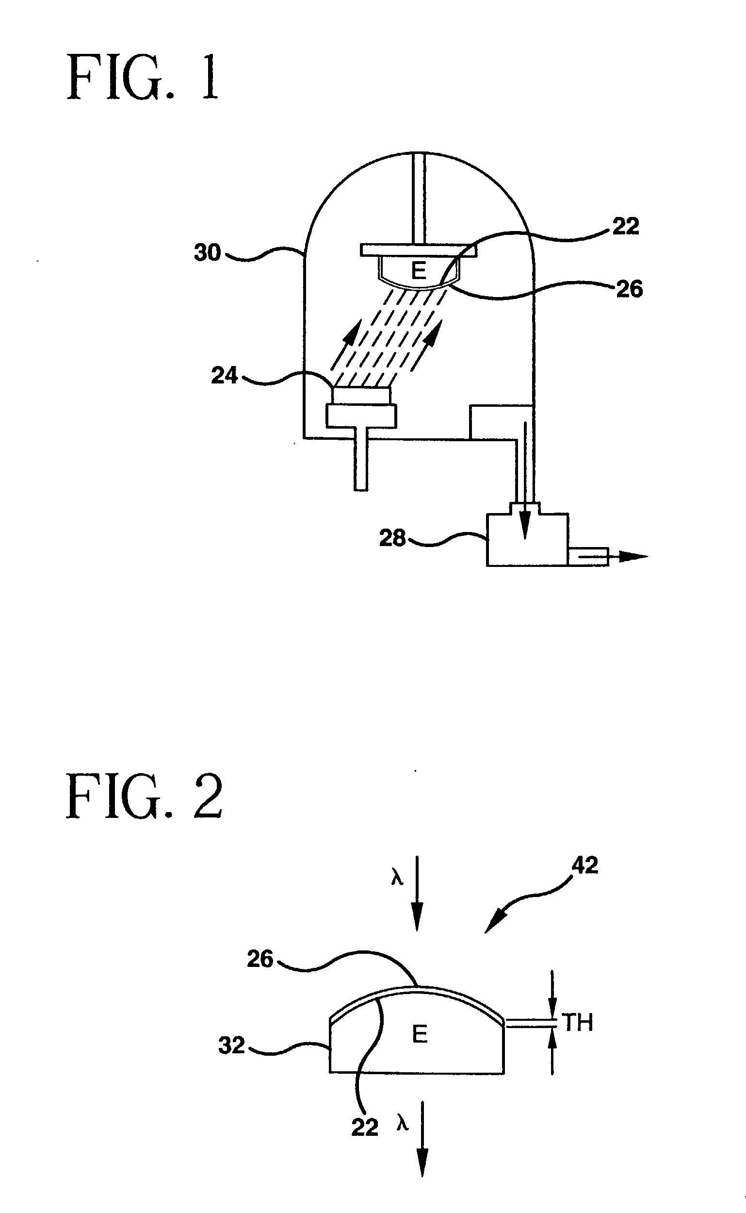
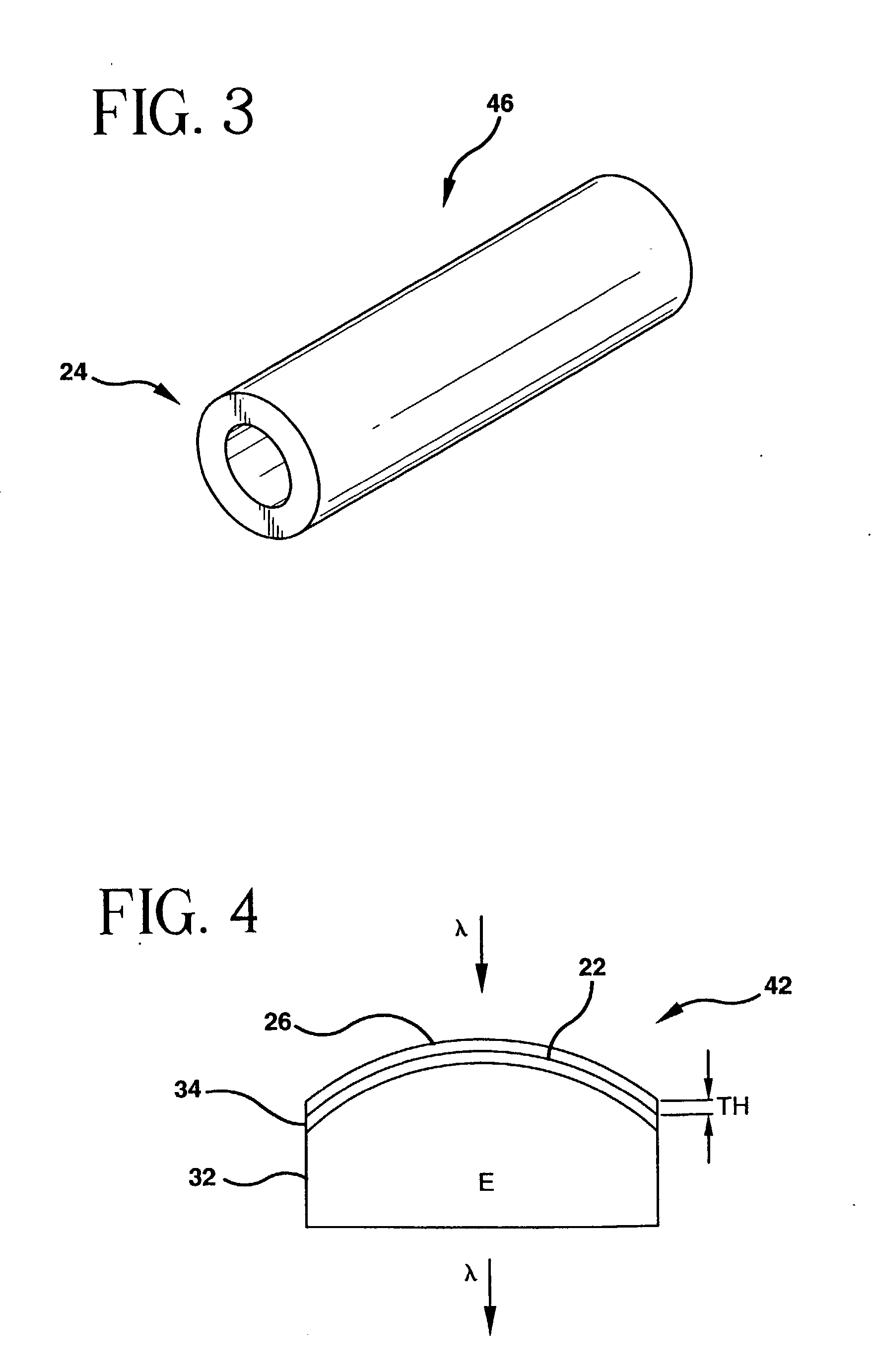
The invention provides coated optical lithography elements and methods of coating optical elements, and particularly optical photolithography elements for use in below 240 nm optical photolithography systems utilizing vacuum ultraviolet light (VUV) lithography wavelengths no greater than about 193 nm, such as VUV projection lithography systems utilizing wavelengths in the 193 nm or 157 nm region. The optical devices manipulate vacuum ultraviolet lithography light less than 250 nm utilizing a deposited silicon oxyfluoride film. The deposited silicon oxyfluoride optical coating assists in the manipulation of incident light and protects the underlying optical materials, layers, and surfaces.

Description

[0001] This application claims the benefit of U.S. Provisional Application Serial No. 60 / 195,682, filed Apr. 7, 2000, entitled FILM COATED OPTICAL LITHOGRAPHY ELEMENTS AND METHOD OF MAKING, by Robert L. Maier, Lisa A. Moore and Charlene Smith.[0002] 1. Field of the Invention[0003] The present invention relates generally to coated optical lithography elements and methods of coating optical elements, and particularly to optical photolithography elements for use in below 240 nm optical photolithography systems utilizing vacuum ultraviolet light (VUV) lithography wavelengths no greater than about 193 nm, such as VUV projection lithography systems utilizing wavelengths in the 193 nm or 157 nm region.TECHNICAL BACKGROUND[0004] Projection optical photolithography systems that utilize the vacuum ultraviolet wavelengths of light below 240 nm provide benefits in terms of achieving smaller feature dimensions. Such systems that utilize ultraviolet wavelengths in the 193 nm region or 157 nm wave...

Claims


Application Information

Patent Timeline
Patent Type & Authority Applications(United States)
IPC IPC(8): G02B5/20G02B5/28G03F7/20
CPCC03B19/1453C03B19/1461C03B2201/075C03B2201/12C03C3/06C03C17/02C03C17/3452C03C2201/12C03C2201/23C03C2203/46G02B1/105G02B5/208G03F7/70958G02B1/14
Inventor MAIER, ROBERT L.MOORE, LISA A.SMITH, CHARLENE M.
Owner CORNING INC
Learn More