Humidifying gas induction or supply system

a gas induction or supply system technology, applied in the field of humidification gas induction or supply system, can solve the problems of complex system, high implementation cost, and large implementation cost, and place a significant constraint on potential implementation

Inactive Publication Date: 2003-02-06
DESIGN TECH & INNOVATION
View PDF9 Cites 12 Cited by
  • Summary
  • Abstract
  • Description
  • Claims
  • Application Information

AI Technical Summary

Benefits of technology

[0004] Many factors control the efficiency with which chemical energy is converted into useful kinetic energy or electricity, while minimizing the non-productive heat that is always produced alongside. Key variables for maximizing the efficiency of an internal combustion engine include maximizing the pressure built up during the combustion process and minimizing the temperatures of the induction air and the combustion chamber. A cooler-burning engine also offers the environmental advantage of a reduction in the amount of nitrogen oxides emitted as a by-product by the reaction of atmospheric nitrogen with oxygen species during the combustion process.
[0018] Advantageously, the present invention allows the selective augmentation of water vapor into an air induction system, such as within an engine of a car, that is achieved easily (in terms of mechanical and control simplicity) and at relatively (if not insignificantly) low cost. Indeed, the inclusion of the system of the present invention is extremely desirable because it limits pollution emissions from car engines (and the like) while also improving efficiency and performance of such engines.
[0020] Advantageously the current invention allows the addition of water vapor to one or more of the gas streams of a fuel cell particularly in proton exchange membrane fuel cells, preventing the proton exchange membrane from drying out and therefore optimizing the fuel cell performance.

Problems solved by technology

However, the complexity of such a system and the high cost of its implementation have conspired to outweigh the benefits obtained by the process for large-scale commercialization.
More specifically, water injection systems to engine cylinders have previously demanded energy input, precise control and high operating pressures, with any one of these requirements itself placing a significant constraint on potential implementation.

Method used


Image

  • Humidifying gas induction or supply system
  • Humidifying gas induction or supply system
  • Humidifying gas induction or supply system

Examples


Embodiment Construction

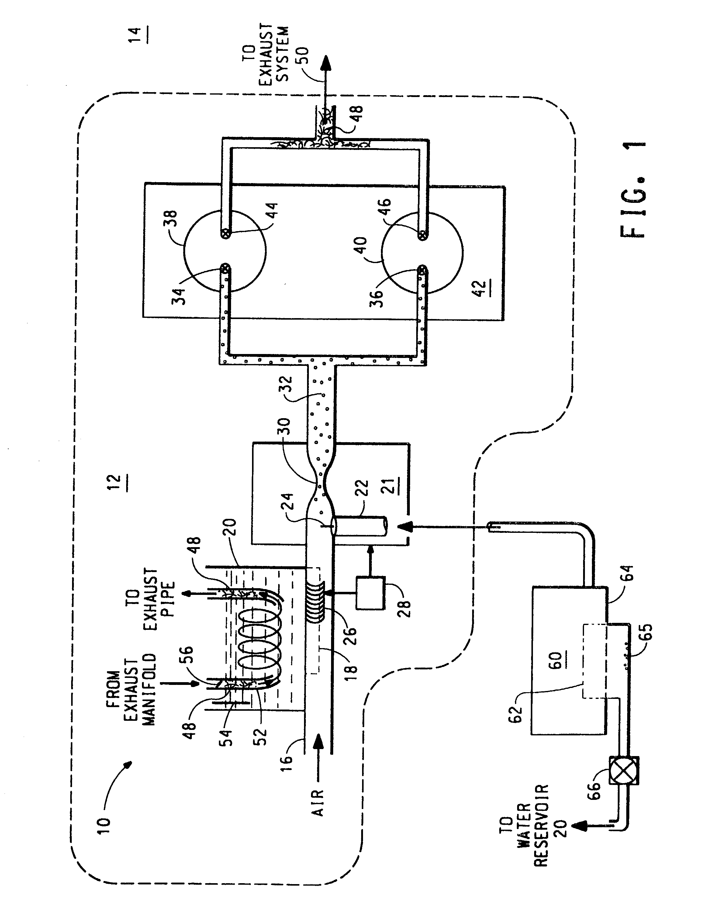
[0026] It has been recognized that engines of cars, for example, develop more power at a nominal revolution rate on damp mornings, with this increase arising as a consequence of dampness in the air. The present invention has identified that there are, in fact, significant advantages and benefits derived from injecting water (in the form of water vapor) into the cylinders of an engine, for example. For example, limited amounts of water vapor in the cylinder during compression and ignition produces an increased compression ratio without suffering the detrimental effects of "pinking" or "knocking". Furthermore, in relation to the overall combustion process within the cylinder, the water vapor cleans the combustion chamber and improves fuel burn (by changing the vapor density and heat capacity of the fuel-air mixture), thereby resulting in lower emissions. Additionally, the presence of water vapor in the combustion chamber has a cooling effect that cools the burn. In other words, the hi...


PUM

PropertyMeasurementUnit
thicknessaaaaaaaaaa
air temperatureaaaaaaaaaa

Abstract

Water vapor is introduced into an inlet air stream (16) of an engine (12), for example, by a pervaporation process through a non-porous hydrophilic membrane (18). A water reservoir (20), which can contain contaminated water, provides a vapor pressure gradient across the hydrophilic membrane (18) into the inlet air stream (16), while the rate of delivery of the water vapor to a cylinder (38-40) is self-regulated by the rate of flow of air across the membrane. The hydrophilic membrane (18) therefore also filters the water from the water reservoir (20) to an extent that pure water vapor is provided to the air inlet stream (16). Delivery of water vapor can nevertheless be controlled using a hood (26) that slides over the hydrophilic membrane to limit its exposed surface area. Alternatively, water vapor is introduced into one or more of the gas streams of a fuel cell by separating the gas stream from the wet exhaust gas stream by a hydrophilic membrane such that moisture passes across the membrane to moisten the gas stream and thereby prevent drying out of the proton exchange membrane.

Description

BACKGROUND TO THE INVENTION[0001] This invention relates, in general, to humidifying gas induction or supply systems and particularly, but not exclusively, to a humidifying air induction or supply system of an internal combustion engine and a humidifying gas induction or supply system for a fuel cell.SUMMARY OF THE PRIOR ART[0002] In energy conversion systems in general, a fuel and an oxidant are combined to provide energy. In this process, chemical energy is converted into kinetic energy or electricity, as well as heat.[0003] In internal combustion engines, including two-stroke, four-stroke, rotary and diesel motors for example, fuel-air mixtures are burnt to provide this chemical energy. Prior to combustion, the fuel may be dispersed into the induction air stream by means of direct injectors or by a carburetor, and the combustion itself may be triggered by an electrical spark, a glow-wire or simply by the heat of compression of the fuel-air mixture. In all internal combustion engi...

Claims


Application Information

Patent Timeline
Patent Type & Authority Applications(United States)
IPC IPC(8): B01D69/08F02M25/032F02B47/04F02M25/022F02M25/028F23C99/00F23L7/00F24F6/00H01M8/04H01M8/10
CPCH01M8/04119H01M8/04156H01M2300/0082F02M25/028Y02T10/121F02M25/0224Y02E60/50Y02T10/12
Inventor TONKIN, MARK CHRISTOPHERYOUNG, MARK ANDREWSCHUCHARDT, MARK ELDEN
Owner DESIGN TECH & INNOVATION
Why Eureka
Try Eureka