Gas fryer with improved heat-exchange properties

a technology of heat exchange and gas fryer, which is applied in the direction of lighting and heating apparatus, applications, and ways, can solve the problems of oil degradation, large heat exchange area of gas fryer, so as to improve the uneven temperature of gas fryer, prevent cooking oil degradation, and increase productivity

Inactive Publication Date: 2003-02-20
K K FUJI ENTERPRIZE +1
View PDF5 Cites 69 Cited by
  • Summary
  • Abstract
  • Description
  • Claims
  • Application Information

AI Technical Summary

Benefits of technology

0008] Therefore, it is an object of the present invention to prevent the degradation of cooking oil by improving uneven temperature of a gas fryer. It is

Problems solved by technology

However, the temperature gradient between the inlet and the outlet side of the heat pipe 2 is rather large in these conventional gas fryer, and a part of the heat pipe near the inlet side of the combustion gas is often over-heated (300 to 350.degree. C. in comparison to the setting temperature at 180.degree. C.).
Thus, it is a problem that the unbalanced temperature causes the degradation of the oil.
Further, it is also

Method used


Image

  • Gas fryer with improved heat-exchange properties
  • Gas fryer with improved heat-exchange properties
  • Gas fryer with improved heat-exchange properties

Examples


example 1

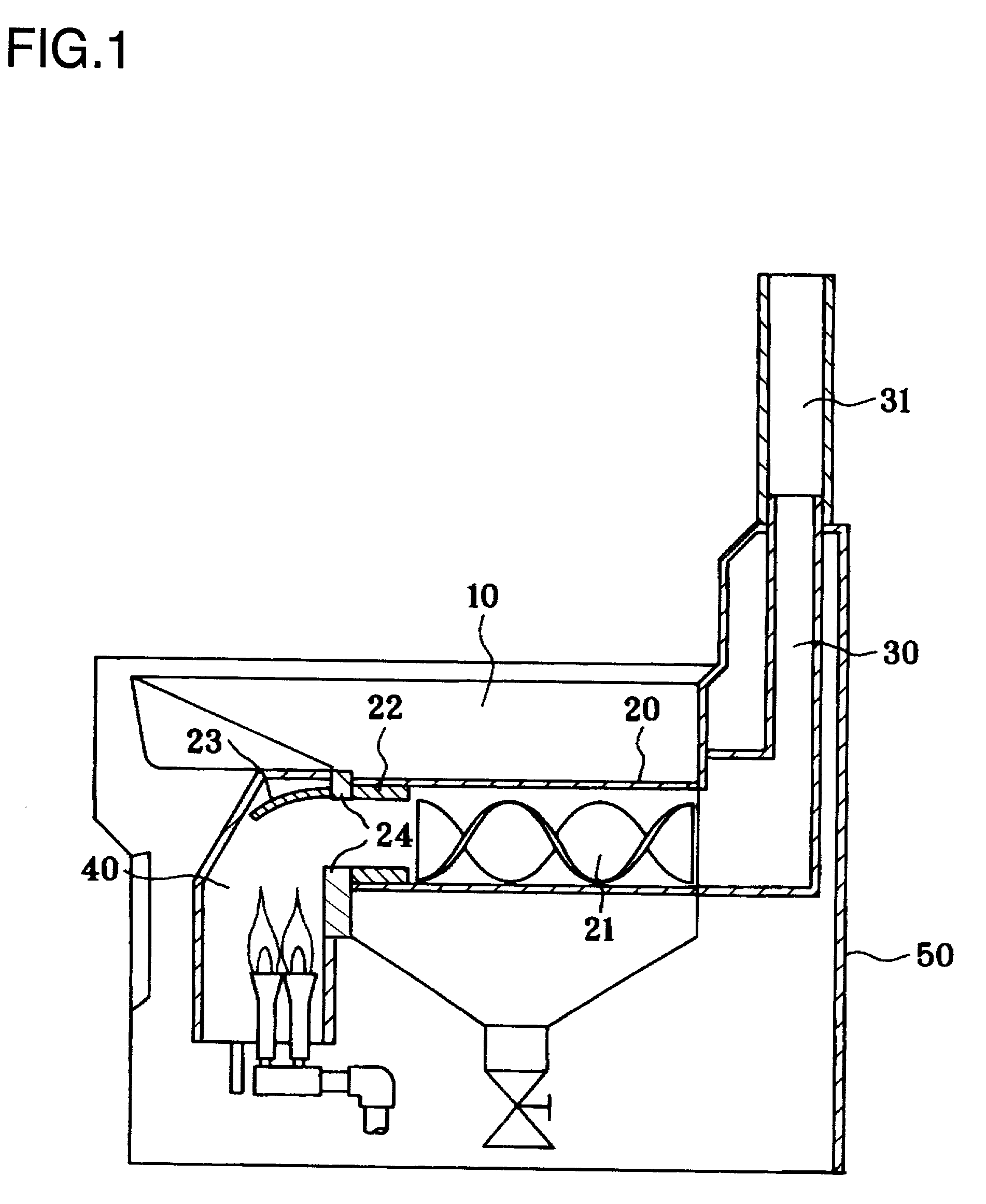
[0071] The oil tank 10 in FIG. 11 was a stainless tank with 390 mm in length, 325 mm in width and 265 mm in depth, in which three heat pipes with 89.1 mm in outside diameter, 1.2 mm in thick and 325 mm in length were provided in left, right and center of the oil tank respectively. The thermocouples were attached on the upper surfaces of both the combustion gas inlet and outlet sides of the heat pipes 20. 22 litter of soybean oil were poured in the oil tank 10, so that the heat pipes were soaked in the oil approximately 65 mm under the surface of the oil. Four or six burners were provided in the combustion chamber 40. Energy consumption was calculated by measuring the amount of gas flow. The temperature of the oil was measured by thermocouple at the position of about 15 mm above of the heat pipe in the approximate center of the oil tank. The temperature of the exhaust gas was measured by thermocouple at the combustion gas outlet of the flue.

[0072] In the approximate middle of these t...

example 2

[0077] When the temperatures of three heat pipes having the same spiral vane in shape were measured, it was observed that the temperature of the middle heat pipe was higher than that of left and right heat pipes. In addition, the flame of fire from the gas burner tended to converge at the middle. Thus, the thickness of the sleeve, that is, the cross section of the combustion gas inlet side of the heat pipe was changed, and the combustion tests were performed. The conditions of the tests were according to those of Example 1, except that the energy of the combustion gas is 9,430 kcal / h, the length of the spiral vane is approximately 130 mm (two spiral vane of 65 mm in length, having a bidirectionally extended vane from central axis twisted approximately 180 degree in right hand were connected with metal bolts), and the spiral vanes were disposed as the rear edge of the vane fits the outlet edge of the heat pipe. The results are shown in Table 2.

2 TABLE 2 Thickness of the sleeve (mm) l...

example 3

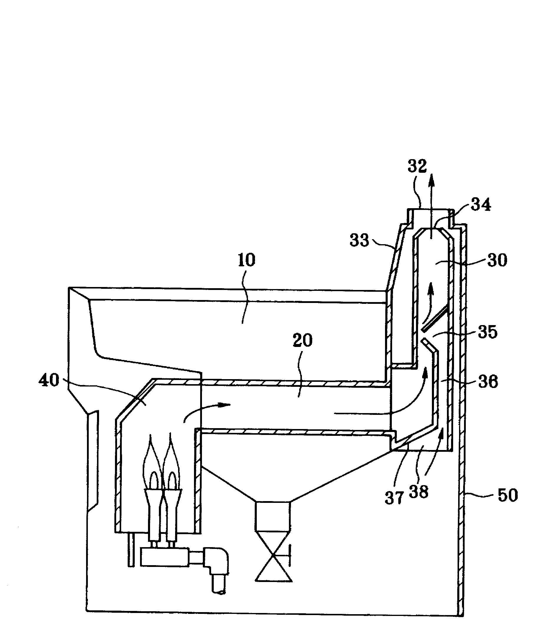
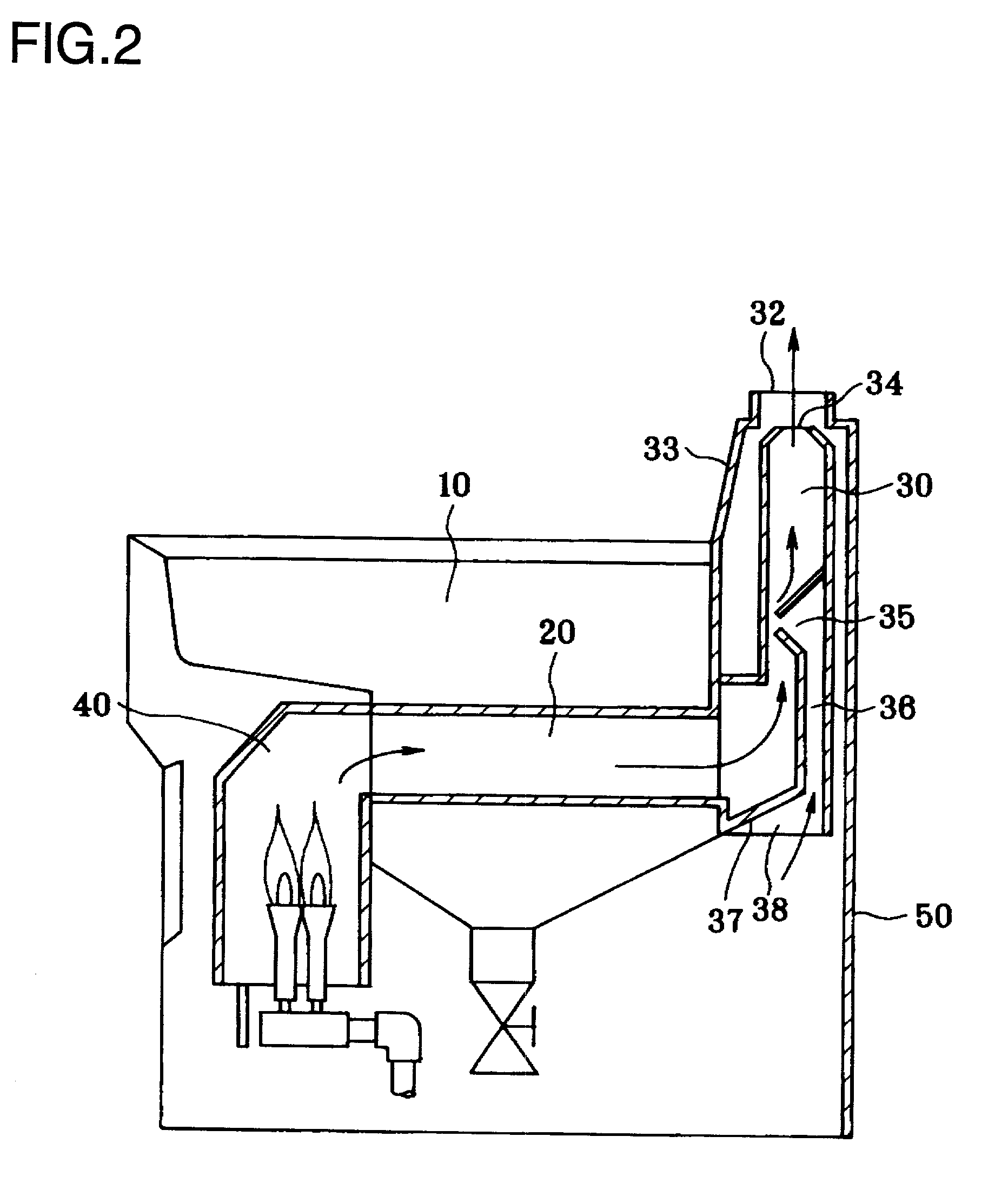
[0079] Another embodiment of the present invention is explained by referring to FIGS. 5 to 7. The apparatus used for the experiment was produced by combining the flue of FIG. 5 with the conventional gas fryer in FIGS. 6 and 7.

[0080] The fryer comprised the oil tank 10 holding 22 liter cooking oil, gas burners of 10,000 kcal / hour, and three heat pipes of 86.1 mm internal diameter.times.325 mm effective length. The area of the inlet opening of fresh air 38 was 3,532 mm.sup.2.times.3, the area of the blowing nozzle was 1,540 mm.sup.2.times.3, and the area of heat exchangers was 13,658 mm.sup.2.times.3. The space between the flue 30 and the backboard 50 was made 20 mm larger than that of the conventional fryer to insulate from the exhaust gas of high temperature. The slit 60 between the exhaust hole 34 and the flue jacket 33 was 5 mm, although there is no slit in the conventional fryer. The temperatures at the lower side 61, and the upper side 62 of the flue 30, and the lower side 63, a...


PUM


Abstract

A gas fryer comprising: a tank for holding cooking oil, a heat pipe located proximate in the middle depth of said tank so that said heat pipe is soaked in said cooking oil, a combustion chamber located at the combustion gas inlet side of said heat pipe, and a flue located at a combustion gas outlet side of said heat pipe, wherein said heat pipe comprises a sleeve fitted in the inner wall of said heat pipe, and a spirally shaped mixer installed in said heat pipe, and wherein said flue comprises an introduction system of fresh air, said system comprising of a blowing nozzle of the fresh air positioned proximate to a narrowed region located proximate in the middle of said flue along a longitudinal axis, an inlet of fresh air located at a part of said flue, and a passage of fresh air provided along the inner and/or outer wall of said flue was provided.

Description

[0001] The present invention relates to a gas fryer for cooking foodstuffs in cooking oil supplied and heated in an oil tank, more specifically, to a gas fryer comprising a heat pipe in an oil tank and a cooling system for cooling down effectively the exhaust gas from said heat pipe.[0002] Two different types of fryers, that is, a gas fryer and an electromagnetic fryer for cooking foodstuffs in cooking oil are known in the art. A typical gas fryer is a device of heating oil through heat pipes in the oil tank by the combustion gas of burning liquefied natural gas (LNG) or liquefied petroleum gas (LPG). On the other hand, an electromagnetic fryer is a device of heating oil by electromagnetic induction through the heat pipe generating heat by the electric current of a coil. In general, the recovering time (the time for recovering the temperature of oil, from a decreased temperature by adding foodstuffs into the oil tank, to a working temperature) of the gas fryer is shorter than that o...

Claims


Application Information

Patent Timeline
IPC IPC(8): A47J37/12
CPCA47J37/1247
Inventor YAMAMOTO, OSAMUTERABE, YOSHIHIRO
Owner K K FUJI ENTERPRIZE
Why Eureka
Try Eureka