
Spectral inversion and chromatic dispersion management in optical transmission systems

a technology of optical transmission system and chromatic dispersion, applied in electromagnetic transmission, electrical equipment, transmission, etc., can solve the problems of increasing the risk of fiber optic transmission system impairment, significant power penalty, and increasing optical signal distortion

Inactive Publication Date: 2003-06-26
SPECTRALANE
View PDF4 Cites 27 Cited by
  • Summary
  • Abstract
  • Description
  • Claims
  • Application Information

AI Technical Summary

Benefits of technology

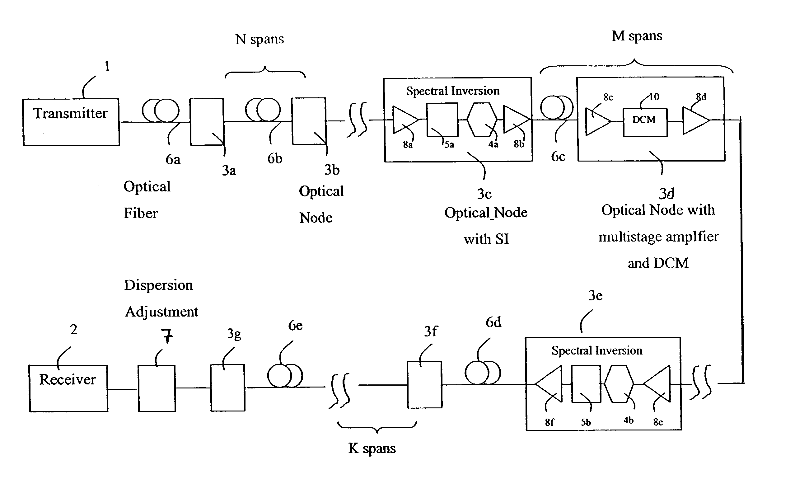
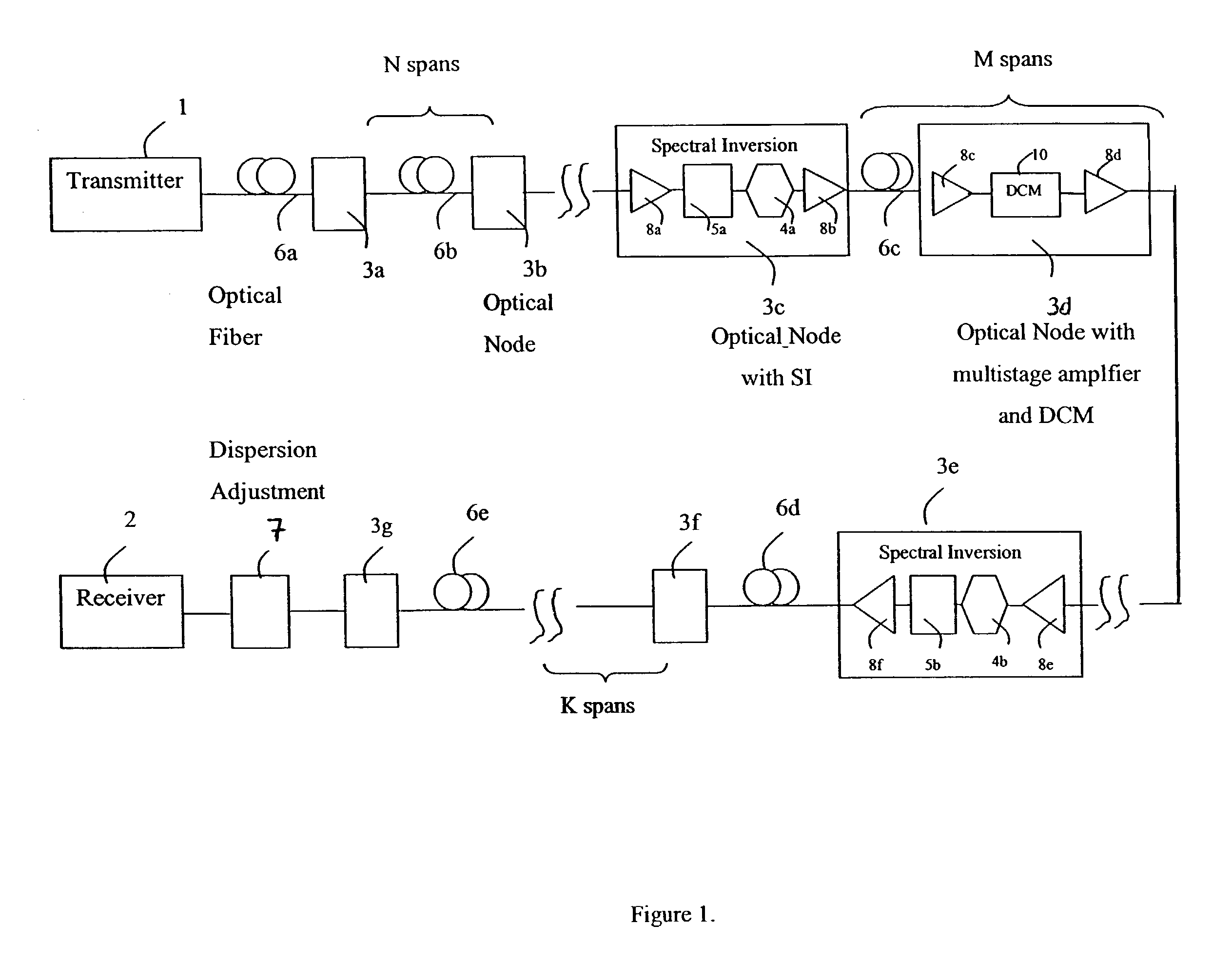
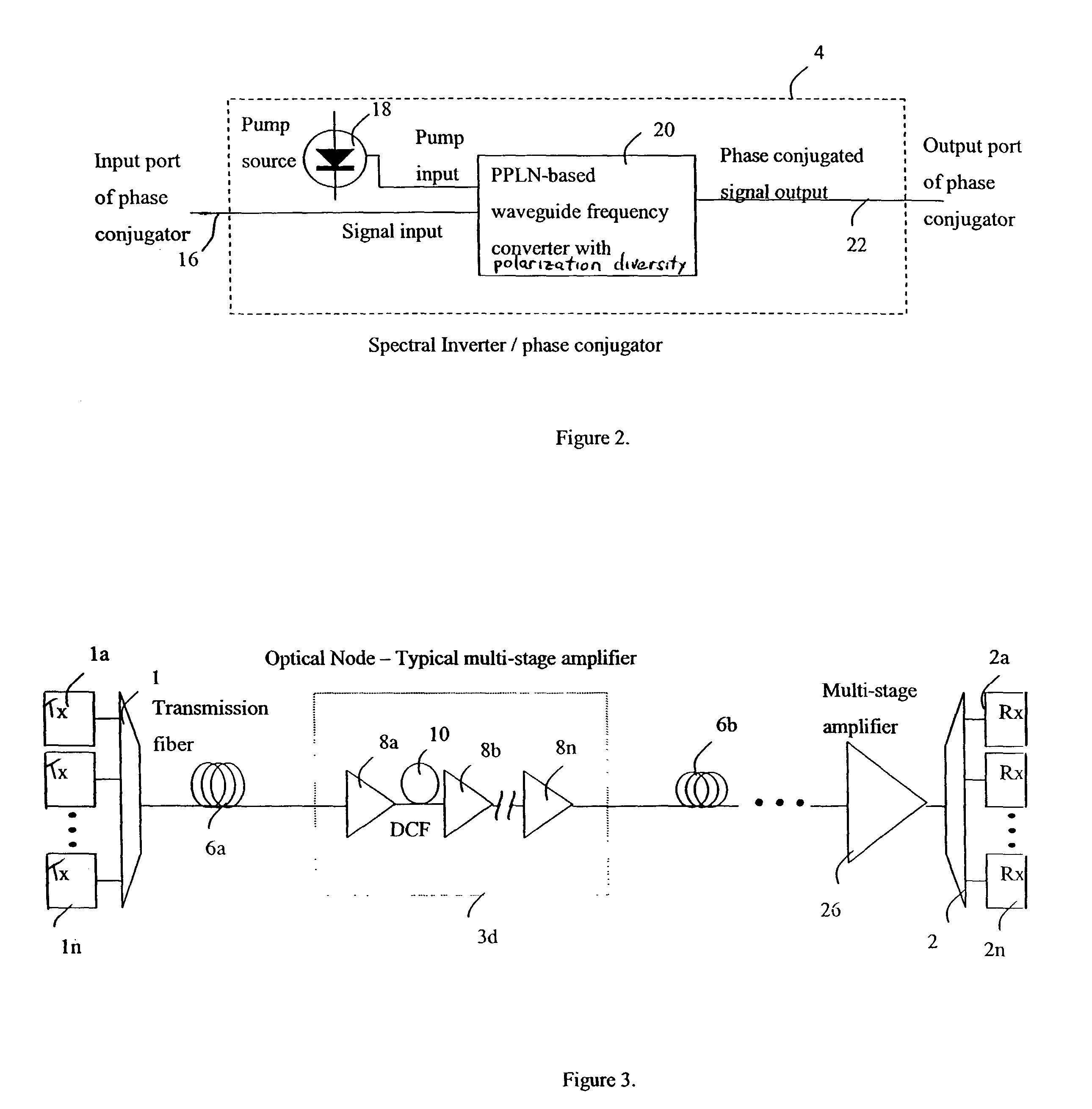
[0019] This provides, in combination, dispersion management and spectral inversion to correct for nonlinear and dispersive effects that degrade performance in a fiber transmission system. The performance is optimized for the right amount of dispersion on a per-segment basis, given a starting value for fiber launch power, which is usually determined by the amplifier noise floor and the transmission distance. Because of the nonlinear effects in the fiber, the amount of compensation may not be the exact amount predicted by simply calculating the fiber dispersion per segment times the number of segments. By either under- or over-compensating dispersion or even removing it completely, depending on the span, better overall signal performance is achieved. Optimization here refers to system performance metrics such as bit-error-rate (BER), or Q factor (related to the signal to noise ratio or SNR) at the receiver. After the dispersion map has been optimized, one or more spectral inverters (SI) are inserted at various positions in the span. The number of SI elements and the exact location(s) is / are case dependent as well. A further dispersion adjustment associated with the SI is used to further optimize performance. One possibility is locating the dispersion adjustment at the location of the spectral inversion (which is convenient from the network operator's point of view), although the dispersion adjustment could be placed elsewhere in the span as well. The dispersion adjustment aligns and / or compresses the signal pulses to achieve adequate cancellation of interchannel and intrachannel nonlinear effects while coping with the effects of higher order dispersion (such as dispersion slope) that could arise from frequency shift during conjugation. At the receiver, more dispersion adjustment is typically used for correction of residual dispersion accumulated during propagation. Other fiber launch powers should also be tested and the optimization described above repeated until the performance is maximized. The insertion of the spectral inversion for fiber nonlinearity suppression often allows for higher launch power, which usually offers advantages in long haul applications.

Problems solved by technology

Generally, the higher the data rate and the denser the wavelength spacing, the more susceptible a fiber optic transmission system is to impairments.
The changes in phase and frequency distributions are translated to amplitude modulation by the fiber dispersion, yielding significant power penalty in most common square law direct detection systems at the optical receivers.
Effects such as chromatic dispersion and the Kerr nonlinearity both lead to increasing optical signal distortion as a function of transmission distance.
Such O-E-O (optical to electrical to optical) repeaters are relatively expensive and complicated.
The main problem with prior art is not effectiveness but rather feasibility and practical use in a cost effective manner in real networks.
For example, constant power situations are not easy to accomplish since real networks have regular amplifier spacing of orders of tens of kilometers and the fiber loss (typically 0.2 dB / km) spoils any realistic expectations for constant power.
Changing the fiber type (to ones with special dispersion functions and higher order dispersion characteristics) in alternate spans or portion of spans is obviously not feasible in installed networks and undesirable, expensive, and complex even in new installations.
All of these techniques are impractical in current networks.
Prior art does not disclose combining the properties of phase conjugation with dispersion management throughout the propagation transmission span to control nonlinear effects in multiple-wavelength systems.
However, a more general problem is addressing all fiber nonlinear effects simultaneously and practically in a wavelength division multiplexing (WDM) system.
With the proliferation of dense WDM, this is actually a significant issue which needs to be addressed before one can expand transmission capacity and distance.
Earlier spectral inversion attempts either failed to provide optimal solutions of both intrachannel and interchannel nonlinear effects in multi-wavelengths systems (they were restricted to single channel SPM type distortion), or such solutions lacked practical implementation feasibility, as described above.
In the prior art it has been shown that using an SI in a system without dispersion management can lead to unacceptably large timing jitter at the receiver.
The uncompensated dispersion in such a system converts the frequency noise of the pump laser into timing jitter on the received signals.
The performance may or may not be adequate depending on the span.
As such, the exact mid-point may not be available even if it were the best point of symmetry.
The reason from a practical point of view is that most networks already have dispersion compensation elements installed, and hence that degree of freedom may not be available for independent optimization.

Method used


Image

  • Spectral inversion and chromatic dispersion management in optical transmission systems
  • Spectral inversion and chromatic dispersion management in optical transmission systems
  • Spectral inversion and chromatic dispersion management in optical transmission systems

Examples


example

Mixed Fiber, 10 Gbps Transmission

[0059] This example demonstrates the importance of the parameter space choices in the spectral inversion configuration for optimization of signal quality. The system is a mixed fiber span, having of 24 segments of SMF28 fiber and 8 segments of TrueWave fiber for a total of 2560 km transmission distance (32.times.80 km). Five channels spaced at 25 GHz at constant launch power of 0 dBm per channel were assumed. (These simulations use conventional computer software for optical design.)

[0060] The optimal values for dispersion were 95% for the SMF28 fiber portion and 120% for the TrueWave fiber portion (relative to the expected value for dispersion compensation from linear assumptions). The Q performance with only dispersion optimization was found at the receiver to be 11 dB.

[0061] Adding two spectral inversions, at the mid-point of each fiber portion (12th and 28th segments), with appropriate dispersion adjustment at the optical nodes huts (20% and 60%, ...


PUM


Abstract

A system and method for improving performance of optical fiber networks. The combination of optical spectral inversion and dispersion management enhances performance in optical fiber transmission by controlling the effect of fiber nonlinearities. An optical fiber link, which includes a number of segments or spans, each with a length of fiber and an optical node (typically consisting of at least an amplifier), is provided with at least one spectral inverter, or an optical phase conjugator, connected in the link. Additionally, each span is provided with an amount of dispersion compensation, such as a length of appropriately chosen fiber, to compensate for dispersion as well as other distortion from dispersion's interplay with fiber nonlinear effects. Additional dispersion adjustment is provided in association with the spectral inverter. The location of the spectral inverter (or inverters) and the amount of appropriate dispersion compensation are designed along with other transmission parameters for optimized system performance.

Description

[0001] This application claims priority to U.S. Provisional Application No. 60 / 342,266, filed Dec. 21, 2001.[0002] This disclosure pertains to fiber optic communications, and to fiber optic communications systems with spectral inversion.DESCRIPTION OF THE PRIOR ART[0003] Optical communications is a well-known field. Typically, present day optical communications transmit high-bit-rate digital data (2.5-40 Gbps and beyond) over silica glass fiber (or optical fiber, as it is commonly called) by modulating a laser or other optical source. Such fibers are known to have broad bandwidth and can carry therefore multiple high data rate channels at different frequencies, sometimes with a spectral efficiency as high as 1 bit / Hz.[0004] The transmission distance that can be met for a given data rate signal depends on the impairments in a fiber optic transmission system. Typical impairments include loss, chromatic dispersion, polarization mode dispersion, polarization dependent loss, and nonlinea...

Claims


Application Information

Patent Timeline
Patent Type & Authority Applications(United States)
IPC IPC(8): H04B10/18
CPCH04B10/2531
Inventor PAPAPARASKEVA, PARASKEVASWOODS, GARY L.PITT, DONALD A.
Owner SPECTRALANE
Learn More