

FGD gypsum dewatering improvement through crystal habit modification by carboxylic acids
a technology of carboxylic acid and crystal habit modification, applied in the field of fgd gypsum dewatering, can solve the problems of early installation plagued by scaling problems
- Summary
- Abstract
- Description
- Claims
- Application Information
AI Technical Summary
Benefits of technology
Problems solved by technology
Method used
Image

Examples
Embodiment Construction
[0064] A preferred embodiment of the present invention relates to a flue gas desulfurization plant treating gases from cement manufacturing plant. The primary objective of the FGD plant is to remove sulfur dioxide by wet scrubbing of the flue gas from rotary kiln and alkali bypass. In addition, a portion of the dust and most of the halide gases are also removed.
[0065] The flue gas desulfurization plant consists of the following major sub-systems:
[0066] Absorbent feeding and preparation system
[0067] Absorption section
[0068] Dewatering section
[0069] These sub-systems are described in the following pages, while FIGS. 3 and 4 show the process flow diagrams.
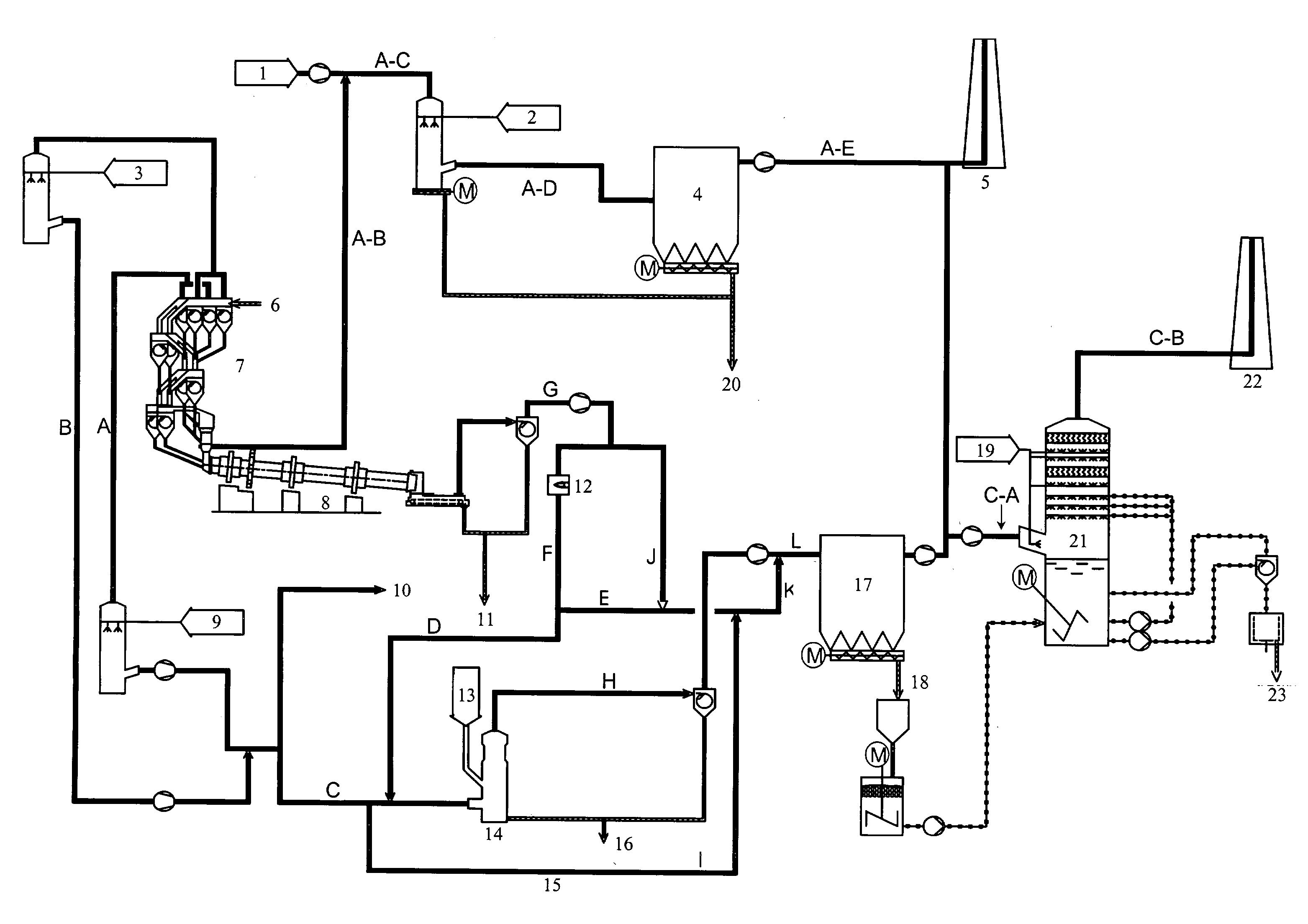
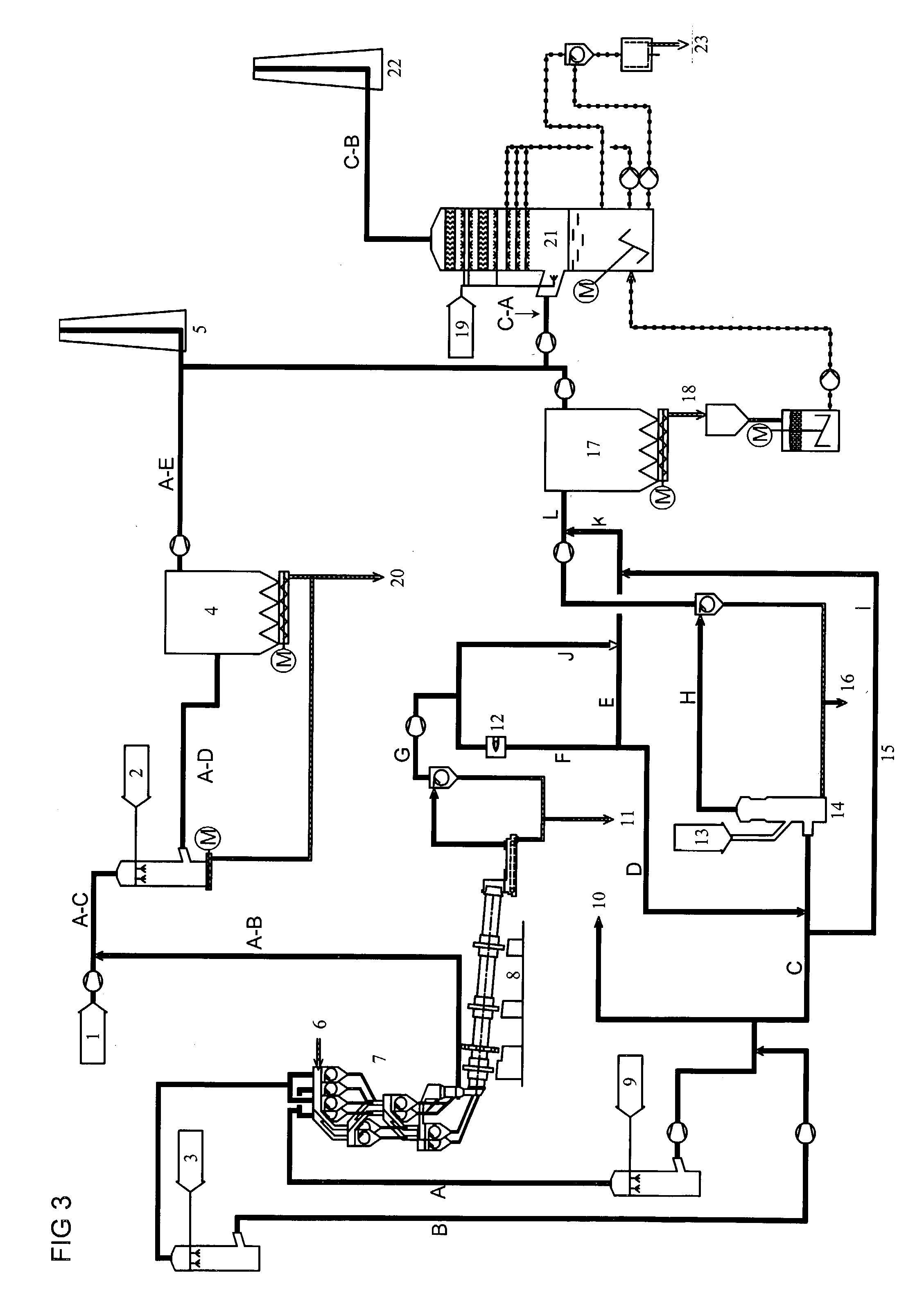
[0070] FIG. 3 shows the schematic of cement plant where gas streams from alkali bypass, and rotary kiln are introduced to wet scrubbing system.
[0071] FIG. 4 shows process flow diagram for flue gas desulfurization system based on limestone forced oxidation where citric acid is added for gypsum crystal modification.
[0072] Absorbent feed...
PUM
| Property | Measurement | Unit |
|---|---|---|
| Length | aaaaa | aaaaa |
| Fraction | aaaaa | aaaaa |
| Fraction | aaaaa | aaaaa |
Abstract
Description
Claims
Application Information