Cooling device for cooling components of the power electronics, said device comprising a micro heat exchanger

a technology of power electronics and cooling components, which is applied in the direction of domestic cooling apparatus, lighting and heating apparatus, basic electric elements, etc., can solve the problems of inferior efficiency of electronic components, significant rise in component temperature, and inability to meet the needs of cooling components, etc., to achieve large heat flow, solve problems, and reduce the effect of heat loss

Inactive Publication Date: 2003-09-25
ROBERT BOSCH GMBH
View PDF38 Cites 22 Cited by
  • Summary
  • Abstract
  • Description
  • Claims
  • Application Information

AI Technical Summary

Benefits of technology

0013] Important advantages result from a suitable coolant flowing through the micro heat exchanger, the coolant evaporating at the desired component temperature. Because of a plurality of flow-through channels, micro heat exchangers have a large heat transfer surface and, when a suitable coolant flows through them, are thus in the position to dissipate large heat flows at the desired temperature. In addition, the temperature difference along the cooling channels is smaller than in single-phase convective heat transfer because a large portion of the heat is transferred at the phase transition temperature. Thus, uniform temperature distribution takes place also in the area of the components to be cooled. Because of their small channel diameter micro heat exchangers are suitable for operation under high pressures. Sealing problems may also be solved more easily than in boiling bath cooling.

Problems solved by technology

The methods of cooling power electronics components, utilized hitherto, have disadvantages due to the large volumes and weights of the solid heat sinks, which are 30 mm thick, for example.
Because of the limited cooling effect of such solid heat sinks, large waste heat flows of the power electronics components result in a significant rise in component temperatures.
High component temperatures cause an inferior efficiency of the electronic components and may result in the destruction of the same.
By utilizing boiling bath cooling, this is only possible to a limited degree.

Method used


Image

  • Cooling device for cooling components of the power electronics, said device comprising a micro heat exchanger
  • Cooling device for cooling components of the power electronics, said device comprising a micro heat exchanger

Examples


Embodiment Construction

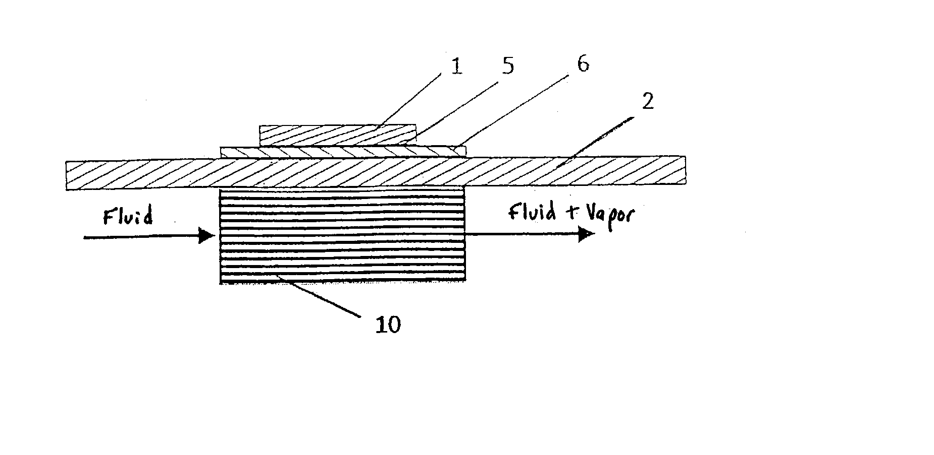
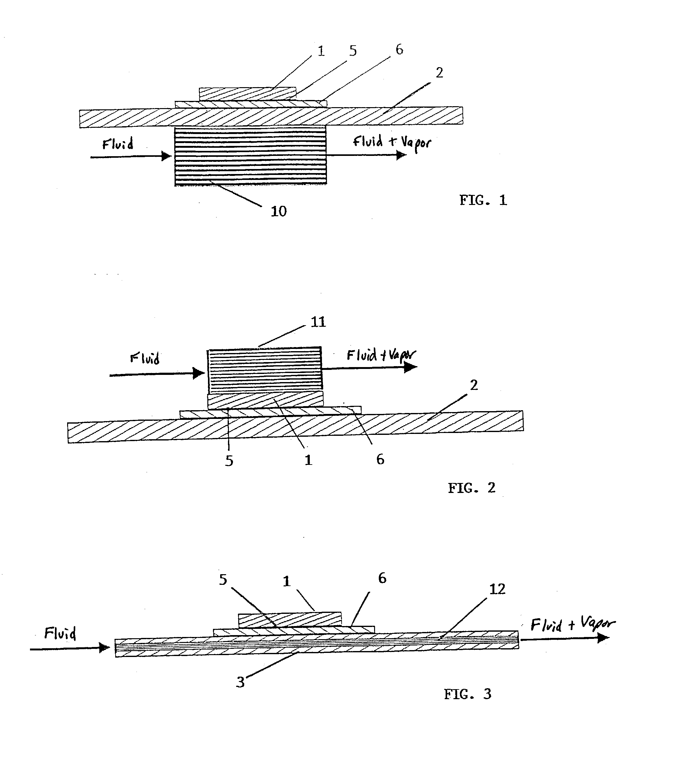
[0018] Three variants of a cooling device according to the present invention for cooling of components of power electronics are illustrated in FIGS. 1 through 3.

[0019] In a first exemplary embodiment, shown in FIG. 1, a micro heat exchanger 10 is situated on the back of an insulating circuit board substrate 2 opposite a component 1 to be cooled, the component being connected to circuit board substrate 2 on the front of substrate 2 via an electrical and thermal contact 6 and a solder layer 5. A heat flow is released in power electronics component 1, the heat flow being transferred to micro heat exchanger 10 via solder 5, electrical and thermal contact 6, and circuit board substrate 2 (board for short).

[0020] Fluid coolant which is slightly undercooled is fed to micro heat exchanger 10. Initially the coolant heats up to boiling and then starts boiling in the channels of micro heat exchanger 10. This is also called flow boiling of a saturated fluid.

[0021] Flow boiling of an undercooled...


PUM


Abstract

The present invention relates to a cooling device, in particular for cooling of components of power electronics, using a coolant which flows through a micro heat exchanger (10) having a good heat contact with the component (1), and wherein the coolant is selected in such a way that it evaporates in the micro heat exchanger (10) at the desired component temperature.

Description

BACKGROUND INFORMATION[0001] The present invention relates to a cooling device, in particular for cooling of components of power electronics, using a coolant which flows through a micro heat exchanger having a good heat contact with the component.[0002] Such a cooling device has been described in INT. J. Heat Mass Transfer, volume 37, No. 2, pages 321-332, 1994, by M. P. Bowers and I. Mudawar, under the title: "High flux boiling in low flow rate, low pressure drop mini-channel and micro-channel heat sinks."[0003] Generally, components or modules of power electronics, such as pulse-controlled inverters for example, are presently predominantly cooled using solid heat sinks made of aluminum or copper. Heat is dissipated here via a liquid coolant which flows through bore holes in the heat sinks.[0004] Alternative heat dissipation via boiling bath cooling is known for power electronics components. Heat is dissipated here by evaporation of an electrically non-conductive fluid, which has d...

Claims


Application Information

Patent Timeline
Patent Type & Authority Applications(United States)
IPC IPC(8): H01L23/427F25D9/00H05K7/20
CPCH01L23/427H01L2924/0002H01L2924/00H05K7/20
Inventor BREUER, NORBERTLEUTHNER, STEPHANHOHL, REINERSATZGER, PETER
Owner ROBERT BOSCH GMBH
Why Eureka
Try Eureka