Packaging material for battery

a battery and packaging technology, applied in the field of packaging materials for batteries, can solve the problems of disadvantageous limitation of the shape of the battery per se, reduced degree of shape freedom, and poor battery body protection properties, and achieve good battery body protection properties

Active Publication Date: 2003-09-25
DAI NIPPON PRINTING CO LTD
View PDF64 Cites 52 Cited by
  • Summary
  • Abstract
  • Description
  • Claims
  • Application Information

AI Technical Summary

Benefits of technology

[0030] The present inventors have now found that a packaging material, for a battery, for forming an armor body adapted for use in such a manner that, in packaging of a battery, a battery body is inserted into the armor body using a polypropylene resin as a sealant layer and the peripheral edge of the armor body is heat sealed for hermetic sealing, can be provided which can prevent short-circuiting between a barrier layer in the armor body and a lead upon the application of heat and pressure necessary for the heat sealing and does not have any fear of causing root cutting in the sealant layer, that is, has excellent insulating properties and has stable hermetic sealing properties.
[0034] The present inventors have now found that a packaging material, for a battery, for forming an armor body adapted for use in such a manner that, in packaging of a battery, a battery body is inserted into the armor body using a polypropylene resin as a sealant layer and the peripheral edge of the armor body is heat sealed for hermetic sealing, can be provided which can prevent short-circuiting between a barrier layer in the armor body and a lead upon the application of heat and pressure necessary for the heat sealing and does not have any fear of causing root cutting in the sealant layer, that is, has excellent insulating properties and has stable hermetic sealing properties.
[0038] The present inventors have now found that a packaging material, for a battery, for forming an armor body adapted for use in such a manner that, in packaging of a battery, a battery body is inserted into the armor body and the peripheral edge of the armor body is heat sealed for hermetic sealing, can be provided which can prevent short-circuiting between a barrier layer in the armor body and a lead upon the application of heat and pressure necessary for the heat sealing and does not have any fear of causing root cutting in the sealant layer, that is, has excellent insulating properties and has stable hermetic sealing properties.
[0041] The present inventors have now found that a production process can be provided for a packaging material, for a battery, which has good battery body protecting properties and can realize highly productive emboss molding process, a content filling / sealing process and other processes.

Problems solved by technology

The conventional armor bodies for batteries, however, have the following problems.
In metal cans, since the outer wall of the vessel is rigid, the shape of the battery per se is disadvantageously limited.
For this reason, since the hardware side is designed according to the battery, the dimension of the hardware used in the battery is disadvantageously determined by the battery and, thus, the degree of freedom in shape is reduced.
A. Stacking the acid-modified polyolefin resin as the innermost layer in the armor body, however, is disadvantageous, for example, in that, as compared with general polyolefin resins, the moldability or fabricability is inferior and, in addition, the cost is higher.
As a result, the aluminum foil as the barrier layer 12' in the armor body 10' often comes into contact (S) with the metal lead 4', resulting in short-circuiting.
As a result, insulation among the battery body, the metal of the lead, and the barrier layer is broken, and a potential difference occurs.
These unfavorable phenomena shorten the service life of the battery.
B. Further, stacking the acid-modified polyolefin resin as the sealant layer in the armor body or the innermost layer in the sealant layer is disadvantageous, for example, in that, as compared with general polyolefin resins, the moldability or fabricability is inferior and, in addition, the cost is higher.
As a result, the aluminum foil as the barrier layer 12' in the armor body 10' often comes into contact (S) with the metal lead 4', resulting in short-circuiting.
As a result, insulation among the battery body, the metal of the lead, and the barrier layer is broken, and a potential difference occurs.
These unfavorable phenomena shorten the service life of the battery.
C. Further, stacking the acid-modified polyolefin resin as the sealant in the armor body is disadvantageous, for example, in that, as compared with general polyolefin resins, the moldability or fabricability is inferior and, in addition, the cost is higher.
The acid-modified polyolefin having a large MI value, however, is a resin which is likely to be collapsed upon exposure to heat and pressure at the time of heat sealing.
As a result, the aluminum foil as the barrier layer 12' in the armor body 10' often comes into contact (S) with the metal lead 4', resulting in short-circuiting.
As a result, insulation among the battery body, the metal of the lead, and the barrier layer is broken, and a potential difference occurs.
These unfavorable phenomena shorten the service life of the battery.
For example, unsatisfactory bonding strength between the barrier layer and the sealant layer is causative of the entry of water from the exterior.
The entry of water causes the corrosion of the aluminum face by hydrofluoric acid produced by a reaction of the electrolyte in the components constituting the battery with the above water and consequently causes delamination between the barrier layer and the sealant layer.
Further, when a resin having a high tensile modulus of elasticity is used in the sealant layer, at the time of emboss molding, the sealant layer often undergoes whitening or slight cracking in its surface.
Further, the molding stability is poor, and pinholes, molding wrinkling, or cracks often occur.
This significantly hinders cycle shortening and often deteriorates the production efficiency.

Method used


Image

  • Packaging material for battery
  • Packaging material for battery
  • Packaging material for battery

Examples


example a1

[0305] Both sides of 20 .mu.m-thick aluminum were subjected to conversion treatment, and an oriented polyester film (thickness 12 .mu.m) was laminated onto one conversion treated side of the aluminum by dry lamination. Next, a sealant layer was laminated onto the other conversion treated side of the aluminum by dry lamination. A pillow-type pouch as an armor body was formed using the laminate thus obtained.

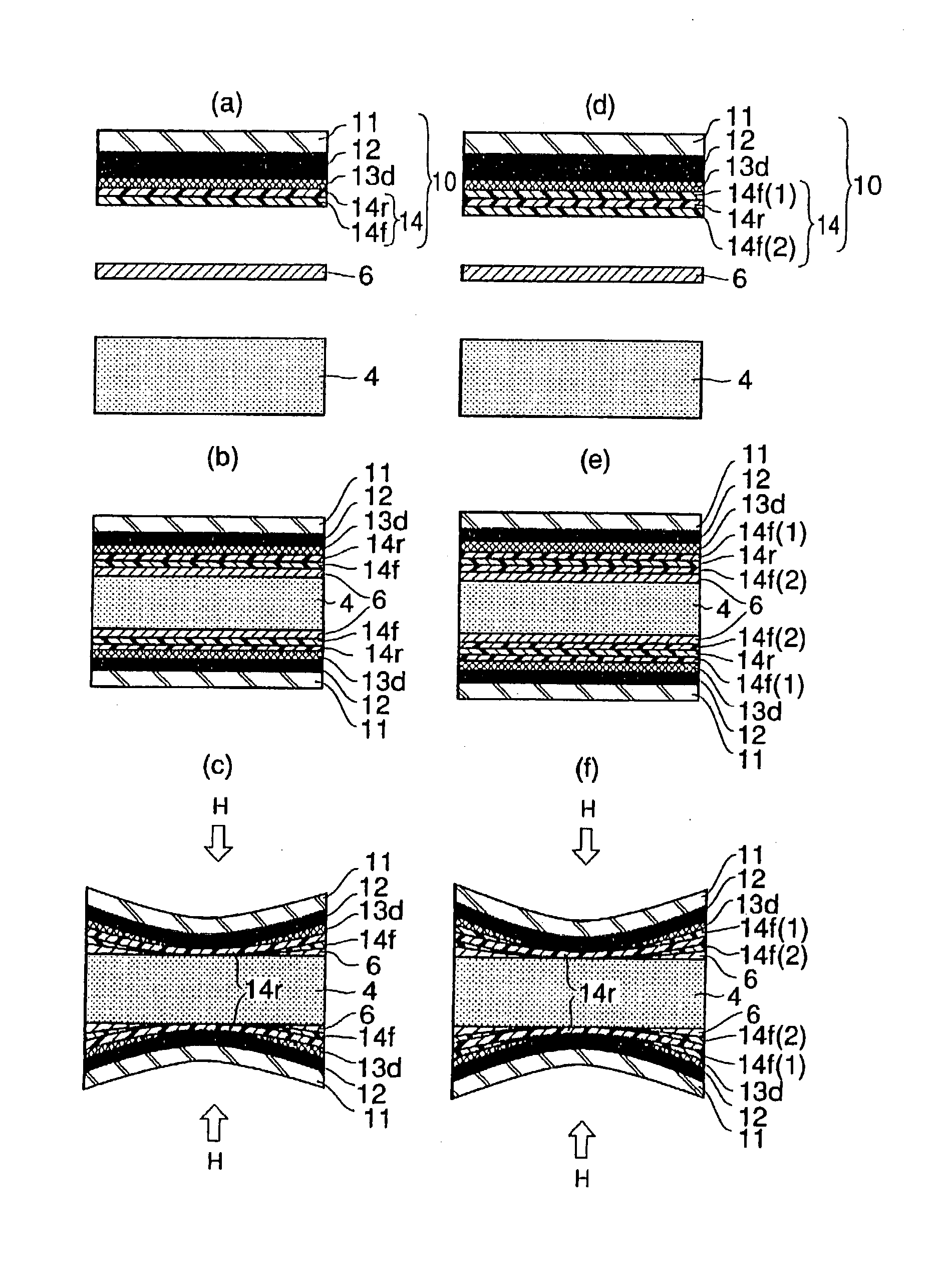
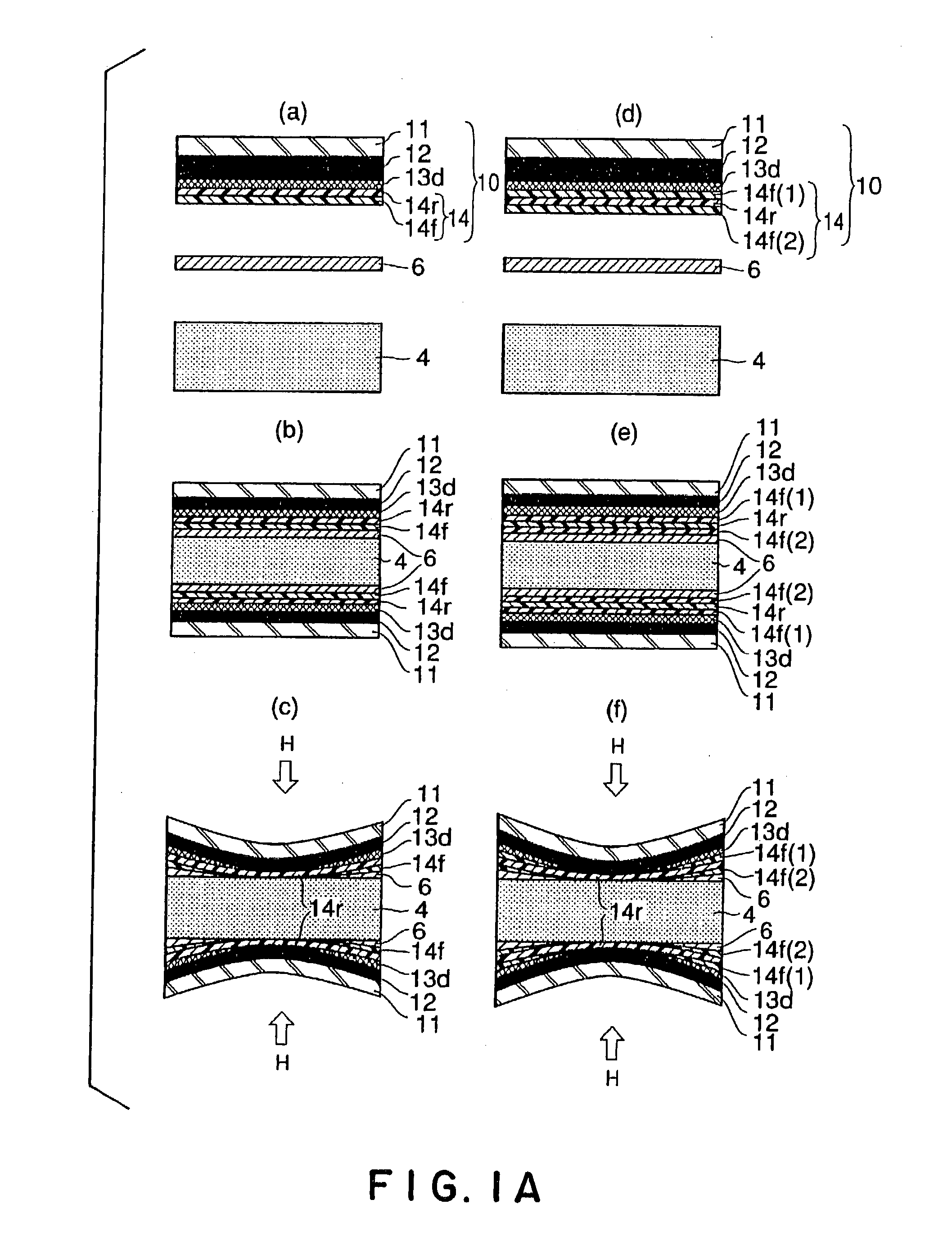
[0306] The sealant layer had a two-layer structure of low-fluidity PP / high-fluidity PP (inner side). These PPs had the following MI and melting point. Figures in brackets indicate layer thickness ratio in coextruded multilayer. This is true of Example A and Comparative Example A which will be described later.

[0307] Low-fluidity PP: MI 0.59 / 10 min, m.p. 147.degree. C.

[0308] High-fluidity PP: MI 20 g / 10 min, m.p. 160.degree. C.

[0309] A battery body was inserted into the above armor body, and the assembly was then heat sealed for hermetic sealing to prepare a sample of Example A1.

example a2

[0310] Both sides of 40 .mu.m-thick aluminum were subjected to conversion treatment, and an oriented nylon film (thickness 25 .mu.m) was laminated onto one conversion treated side of the aluminum by dry lamination. Next, a sealant layer was laminated onto the other conversion treated side of the aluminum by dry lamination. A tray was formed by emboss molding using the laminate thus obtained. An emboss-type armor body was prepared using this tray and the unmolded laminate as a lid.

[0311] The sealant layer had a two-layer structure of low-fluidity PP / high-fluidity PP (inner side). These PPs had the following MI and melting point.

[0312] Low-fluidity PP: MI 3 g / 10 min, m.p. 147.degree. C.

[0313] High-fluidity PP: MI 7 g / 10 min, m.p. 147.degree. C.

[0314] A battery body was placed in the tray in the armor body, and the tray was then covered with the lid. The peripheral edge of the tray was heat sealed for hermetic sealing to prepare a sample of Example A2.

example a3

[0315] Both sides of 40 .mu.m-thick aluminum were subjected to conversion treatment, and an oriented nylon film (thickness 25 .mu.m) was laminated onto one conversion treated side of the aluminum by dry lamination. Next, a sealant layer was laminated onto the other conversion treated side of the aluminum by dry lamination. A tray was formed by emboss molding using the laminate thus obtained. An emboss-type armor body was prepared using this tray and the unmolded laminate as a lid.

[0316] The sealant layer had a three-layer structure of high-fluidity PP {circle over (1)} / low-fluidity PP / high-fluidity PP (inner side) {circle over (2)} . These PPs had the following MI and melting point.

[0317] High-fluidity PP {circle over (1)}: MI 10 g / 10 min, m.p. 147.degree. C.

[0318] Low-fluidity PP: MI 1 g / 10 min, m.p. 160.degree. C.

[0319] High-fluidity PP {circle over (2)}: MI 10 g / 10 min, m.p. 147.degree. C.

[0320] A battery body was placed in the tray in the armor body, and the tray was then cove...


PUM

PropertyMeasurementUnit
melt indexaaaaaaaaaa
widthaaaaaaaaaa
thicknessaaaaaaaaaa

Abstract

Disclosed is a packaging material for forming an armor body for a battery, the armor body being adapted for use in such a manner that a battery body is inserted into the armor body and the peripheral edge of the armor body is then heat sealed for hermetic sealing, the packaging material being a laminate comprising at least a substrate layer, an adhesive layer, a barrier layer, a dry laminate layer, and a sealant layer, characterized in that at least the sealant layer comprises a low-fluidity polypropylene layer having low susceptibility to collapse upon exposure to heat and pressure at the time of heat sealing and a high-fluidity polypropylene layer having high susceptibility to collapse upon exposure to heat and pressure at the time of heat sealing, and the innermost layer is the high-fluidity polypropylene layer. This battery packaging material can impart moisture barrier properties and resistance to contents of the battery.

Description

[0001] 1. Field of the Invention[0002] The present invention relates to a packaging material for a battery, which has moisture barrier properties and resistance to contents of the battery and is usable for batteries with a liquid or solid organic electrolyte (polyelectrolyte), fuel batteries (cells), capacitors and the like.[0003] 2. Background Art[0004] The term "battery" as used in the present invention refers to objects including devices for converting chemical energy to electric energy, for example, lithium ion batteries, lithium polymer batteries, and fuel batteries, or electrolytic capacitors containing liquids, solid ceramics, organic materials or other dielectric materials, for example, liquid capacitors, solid capacitors, and bilayer capacitors.[0005] Batteries are used for applications such as personal computers, portable terminal devices (for example, portable telephones (cellular phones) and PDA), video cameras, electric automobiles, energy storage batteries, robots, and...

Claims


Application Information

Patent Timeline
Patent Type & Authority Applications(United States)
IPC IPC(8): H01M50/178H01M50/186H01M50/193H01M50/197H01M50/55H01M50/557H01M50/562
CPCH01M2/021H01M2/0212Y10T428/24942H01M2/08H01M2/348H01M2/0287Y10T428/31913Y02E60/10H01M50/557H01M50/124H01M50/581H01M50/562H01M50/186H01M50/193H01M50/55H01M50/178H01M50/197
Inventor YAMASHITA, RIKIYAMOCHIZUKI, YOICHIYAMADA, KAZUKIOKUSHITA, MASATAKA
Owner DAI NIPPON PRINTING CO LTD
Why Eureka
Try Eureka