
Acrylic fiber and a manufacturing process therefor

a technology of acrylic fiber and manufacturing process, which is applied in the direction of yarn, transportation and packaging, synthetic resin layered products, etc., can solve the problems of inadequate solvent displacement inside the fiber, inadequate repulsion of cloths, and excessive oriented fibers with a drawback of deterioration of dyeability

Inactive Publication Date: 2003-10-30
MITSUBISHI CHEM CORP
View PDF0 Cites 4 Cited by
  • Summary
  • Abstract
  • Description
  • Claims
  • Application Information

AI Technical Summary

Benefits of technology

The resulting fiber exhibits improved dry strength, elongation, and dyeability, providing a wool-like hand feeling and suitable for various applications, including garments and home furnishings, with enhanced softness and brushing effect.

Problems solved by technology

Coagulation and stretching, therefore, simultaneously occur in the coagulation bath, resulting in formation of a skin layer in a coagulated filament, which leads to inadequate solvent displacement inside the fiber.
A fiber with an uneven orientation between its surface and inside provides a poorly elastic staple fiber, which will give a cloth with an inadequate repulsion.
A fiber with an excessively oriented surface has a drawback of a deteriorated dyeability because the highly oriented surface inhibits diffusion of a dye during a dyeing process.
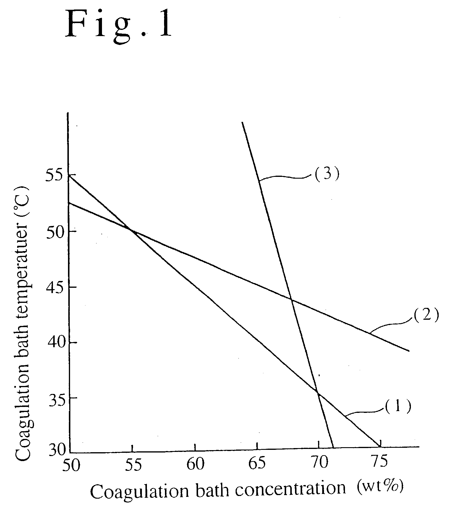
However, when using an aqueous solution of an organic solvent as a coagulation bath, a concentration range of the organic solvent that a skin layer does not form is quite higher, so that a coagulation rate becomes too late to increase a drawing rate of the coagulated filament, leading not only to an extremely lower yield but also to problems such as irregularities and fusion between fibers.
In the technique, color-developing properties of an acrylic fiber are, however, hampered by the additive.
In the technique, while slimy and smooth touch is emphasized, the fiber may have poor softness and color-developing properties.
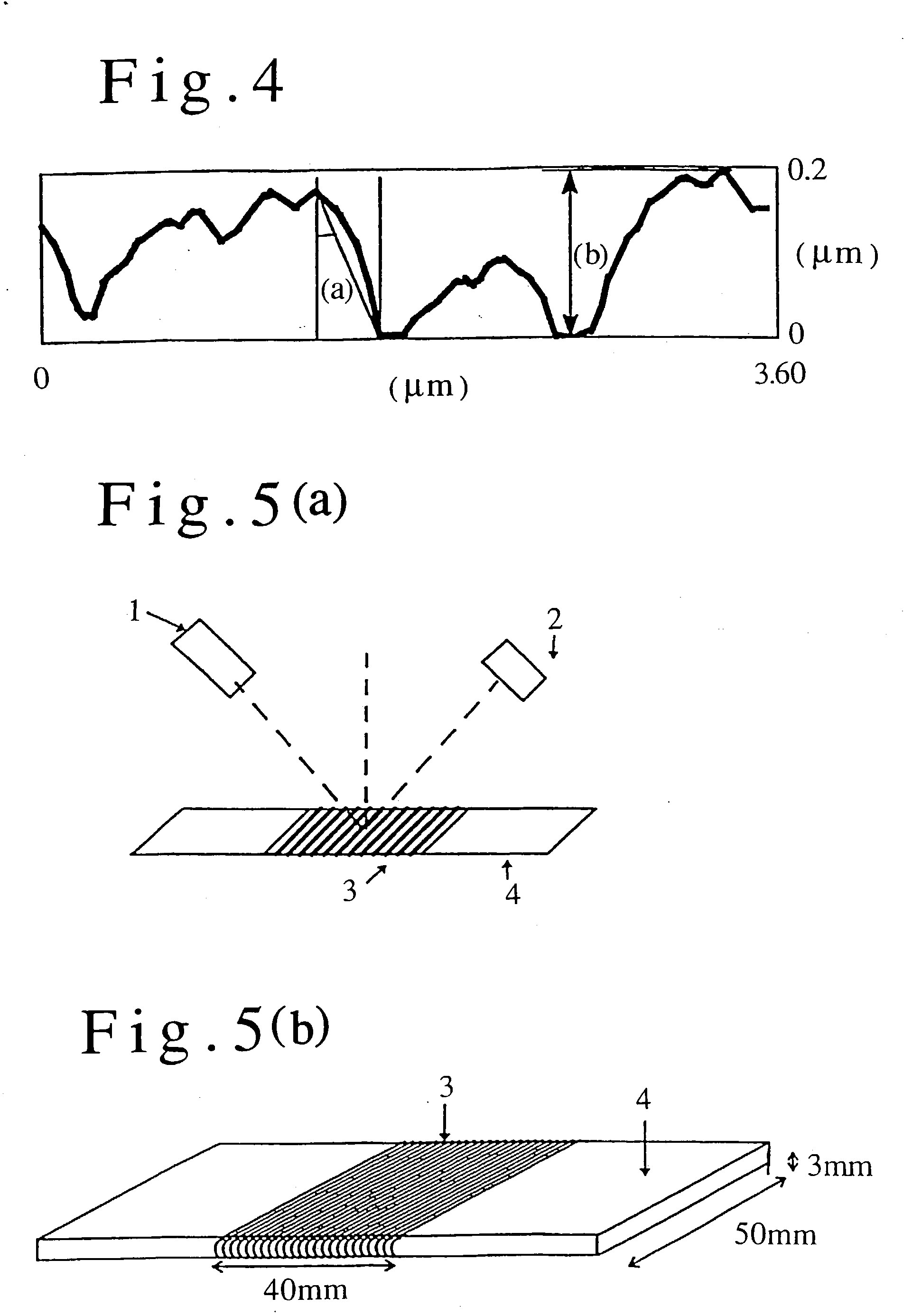
Thus, the fiber surface corrugation is considerably limited.
Thus, it may result in, for example, generating fluffs during spinning.
Furthermore, the fiber may not be easily dried due to water trapped in the openings K1 or the holes K2, leading to a longer drying step during spinning the fiber and thus to a reduced productivity.

Method used


Image

  • Acrylic fiber and a manufacturing process therefor
  • Acrylic fiber and a manufacturing process therefor
  • Acrylic fiber and a manufacturing process therefor

Examples


first embodiment

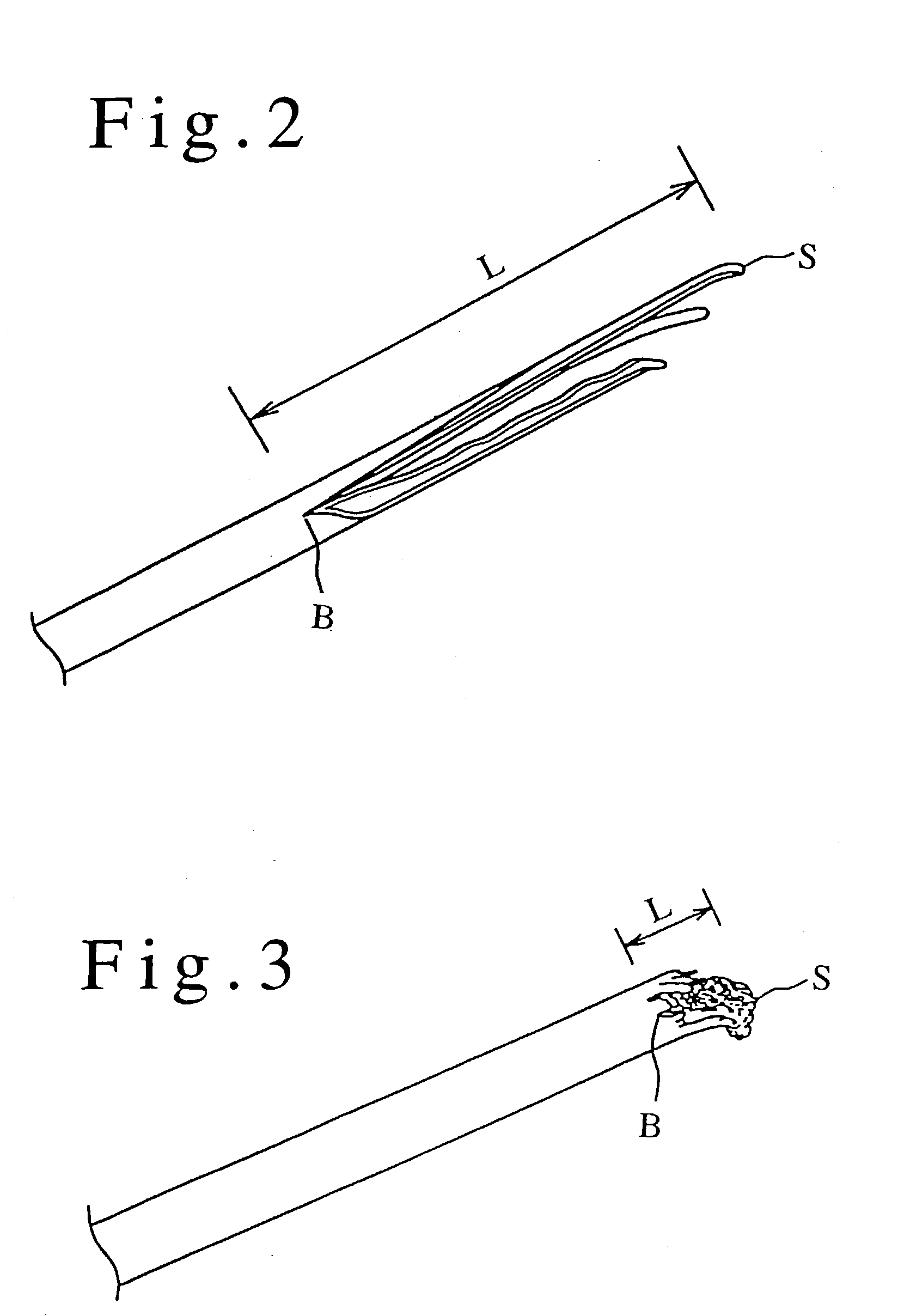
[0044] An acrylic fiber in this invention has a monofilament dry strength of 2.5 to 4.0 cN / dtex, has a monofilament dry elongation of 35 to 50%, and forms a crack with a length of 20 .mu.m or more in its tension rupture lateral surface along the filament axis direction when rupturing the monofilament in a tension test.

[0045] If the monofilament dry strength is lower than 2.5 cN / dtex or the dry elongation is more than 50% in the acrylic fiber, there may be generated many fluffs due to filament breaking during spinning, leading to a deteriorated process passage and significant deterioration in spinnability.

[0046] If the monofilament dry strength is higher than 4.0 cN / dtex or the dry elongation is less than 35%, there may often be inadequate wool-like hand feeling required for an acrylic fiber for an application such as a garment, e.g., a sweater and a home furnishing, e.g., a pile.

[0047] The length of the crack formed along a fiber axis in a tension test is an index indicating differe...

example 1

[0114] A monomer composition consisting of 92 wt % of acrylonitrile and 8 wt % of vinyl acetate was polymerized by aqueous dispersion polymerization using ammonium persulfate-sodium hydrogen sulfite to prepare an acrylonitrile polymer with an average molecular weight of 130,000. The polymer was dissolved in dimethylacetamide to prepare a 24 wt % spinning feed solution.

[0115] The spinning feed solution was discharged into the first coagulation bath consisting of a 50 wt % aqueous dimethylacetamide solution at 40.degree. C. using a spinneret with 40,000 orifice holes and an orifice hole diameter of 60 .mu.m to prepare coagulated filaments. The filaments were drawn from the first coagulation bath with a drawing rate 0.4 times of the discharge linear velocity of the spinning feed solution. Then, the coagulated filaments were immersed into the second coagulation bath consisting of a 50 wt % aqueous dimethylacetamide solution at 40.degree. and was subject to stretching by 1.5 times in the...

example 2

[0118] A staple fiber with a monofilament denier of 3.3 dtex was prepared as described in Example 1, except that the temperatures of the first and the second coagulation bathes were 46.degree. C. and the concentration of the organic solvent was 60 wt %.

[0119] In the above process, the thickness of the skin layer in a coagulated filament drawn from the first coagulation bath was 0.08 .mu.m. The monofilament exhibited a dry strength of 3.5 cN / dtex, a dry elongation of 37%, and the staple fiber exhibited good luster and hand feeling.

[0120] The filament cross section was an essentially perfect circle with a long / short axis ratio of 1.1. Five cracks with lengths of 25 .mu.m, 24 .mu.m, 20 .mu.m, 18 .mu.m and 15 .mu.m along the fiber axis direction were observed in the tension rupture lateral surface.


PUM

PropertyMeasurementUnit
lengthaaaaaaaaaa
elongationaaaaaaaaaa
tilt angleaaaaaaaaaa

Abstract

There is disclosed an acrylic fiber (a) consisting of an acrylonitrile polymer comprising an acrylonitrile unit in at least 80 wt % and less than 95 wt %, (b) having a monofilament dry strength of 2.5 to 4.0 cN / dtex, (c) having a monofilament dry elongation of 35 to 50%, and (d) forming a crack with a length of 20 mum or more in its tension rupture lateral surface along the filament axis direction when rupturing the monofilament in a tension test. The fiber has even orientation in its surface and inside; is significantly improved in dry strength, dry elongation and dyeability; and exhibits wool-like hand feeling. It is, therefore, quite suitable as a synthetic fiber for various applications such as a garment material, e.g., a sweater and a home furnishing material such as a pile.

Description

[0001] This invention relates to an acrylic fiber generally suitable to applications such as a garment and a home furnishing especially pile fabrics.BACKGOUND ART[0002] An acrylic fiber suitable to garments is required to have a good balance between its strength, elongation and dyeability.[0003] An acrylic fiber is generally prepared by wet spinning. It has been a conventional practice to increase a ratio of (a drawing rate of a coagulated filament) / (a discharge linear velocity of a spinning feed solution from a spinneret capillary) in a coagulation bath and to increase a draw ratio in a subsequent step for achieving a high-strength fiber with high orientation.[0004] However, increasing a ratio of (a drawing rate of a coagulated filament) / (a discharge linear velocity of a spinning feed solution from a spinneret capillary) in a coagulation bath, i.e., increasing a drawing rate of a coagulated filament, means a shorter coagulation time for a spinning feed solution in the coagulation b...

Claims


Application Information

Patent Timeline
Patent Type & Authority Applications(United States)
IPC IPC(8): D01F6/18D01F6/38
CPCD01F6/18D01F6/38D01D5/06D01D5/253Y10T428/2978Y10T428/2964Y10T428/2976Y10T428/2913Y10T428/2967Y10T428/2973
Inventor KASABO, YOKIOIKEDA, KATSUHIKOFUJII, YASUYUKIMISHINA, YOSHIHIKOOCHI, RYO
Owner MITSUBISHI CHEM CORP
Learn More