Vaporizer and apparatus for vaporizing and supplying

a technology of vaporizers and vaporizers, applied in the direction of combustion-air/fuel-air treatment, combustible gas purification/modification, separation processes, etc., can solve the problems of difficult to ensure sufficient supply amount in an industrial scale, difficult to vaporize liquid materials, and difficult to ensure sufficient supply amoun

Inactive Publication Date: 2003-11-13
JAPAN PIONICS
View PDF14 Cites 30 Cited by
  • Summary
  • Abstract
  • Description
  • Claims
  • Application Information

AI Technical Summary

Benefits of technology

[0010] Under such circumstances, the present inventors accumulated intensive extensive research and development in order to solve the above-described problems involved in the prior arts. As a result, the following has been found. Specifically, by providing a pressure loss-inducing portion in a CVD material feed portion or between a liquid flow controller and a vaporizer, it is made possible to reduce and stabilize both the pressure fluctuation in the vaporizer and the flow rate fluctuation in the liquid flow controller and to prevent deposit of the solid CVD material less liable to adhere even if such deposit is generated. Thus, the present invention has been accomplished by the foregoing findings and information.
[0021] The present invention is applied to a vaporizer which vaporizes a liquid CVD material or a liquid CVD material made up of a solution of a solid CVD material in a solvent, and which supplies a CVD apparatus or the like with a vaporized gas. In the case of a decrease in a feed amount of a carrier gas to be supplied accompanying the CVD material employing a solid CVD material, the vaporizer exhibits its effect particularly in view of the capability of reducing and stabilizing both the pressure fluctuation in the vaporizer and the flow rate fluctuation in the liquid flow controller and the capability of preventing the deposit and adhesion of a solid CVD material inside the vaporizer.
[0032] Further, it is preferable for the vaporizer of the present invention to have another carrier gas passageway 12 that exhaust the carrier gas to the vaporizing chamber from the outer peripheral of an outlet of the mixing passageway 11 as illustrated in FIGS. 3, (2) and (4). Furthermore, it is desirable for the exhaust outlet of the carrier gas passageway 12 to be settled in a manner that the direction of the exhaust is slanted toward the exhaust outlet of the mixing passageway 11 to the vaporizing chamber. By the application of the foregoing structure of the CVD material feed portion, a vaporizing efficiency of the vaporizer becomes extremely superior because both the pressure fluctuation in the vaporization chamber and the flow rate fluctuation in the liquid mass flow controller at the timing of vaporizing and supplying decrease less and less, and at the same time, the deposit or adhesion of the solid CVD material in the vaporization chamber is also further reduced.
[0036] Furthermore, synthetic resin such as fluororesin or polyimide based resin, or a cavity is preferably applied as the inner surface of the CVD material feed portion in the vaporizer of the present invention. With regards to a material of construction for contacting with the outside of the vaporizer, metals such as carbon steel, manganese steel, chromium steel, molybdenum steel, stainless steel and nickel steel are preferable. In the case where the inside of the CVD material feed portion is constituted of a synthetic resin, the synthetic resin 15 is deployed as illustrated in FIGS. 3, (1), (2), (3), (5) and (6). Further, in the case where the inside of the CVD material feed portion is constituted of a cavity, the cavity 16 is formed as shown in FIG. 3, (4). By the application of the foregoing structure of the CVD material feed portion, even in the case of employing a solid CVD material dissolved in an organic solvent as the CVD material, any vaporization of only the solvent in a passageway induced by an abrupt elevation of the temperature caused by such a heating device as a heater can be prevented.

Problems solved by technology

However, it is difficult to vaporize a liquid material at a desirable concentration and flow rate in high efficiency without deteriorating the quality thereof, since the liquid material has usually a low vapor pressure, a high viscosity and a vaporizing temperature close to a decomposing temperature.
A solid material, although being capable of assuring highly pure material by being kept at an elevated temperature to sublime itself, makes it extremely difficult to assure sufficient supply amount in an industrial scale.
However, since a solid material has a vaporizing temperature greatly different from that of a solvent, a solvent alone is more apt to vaporize by heating, thereby making it more difficult to vaporize a liquid material.
However, although the foregoing vaporizer and apparatus for vaporizing and supplying have effects of preventing the generation of any deposit of the solid CVD material accompanied with adhesion inside the CVD material supplier, a decrease in a feed amount of a carrier gas to be supplied accompanying the CVD material brings about such disadvantage that a solvent alone is vaporized, in the same manner as the conventional vaporizers, thus causing an anxiety of a solid CVD material to be more prone to be deposited in the vaporizer.

Method used


Image

  • Vaporizer and apparatus for vaporizing and supplying
  • Vaporizer and apparatus for vaporizing and supplying
  • Vaporizer and apparatus for vaporizing and supplying

Examples


example 1

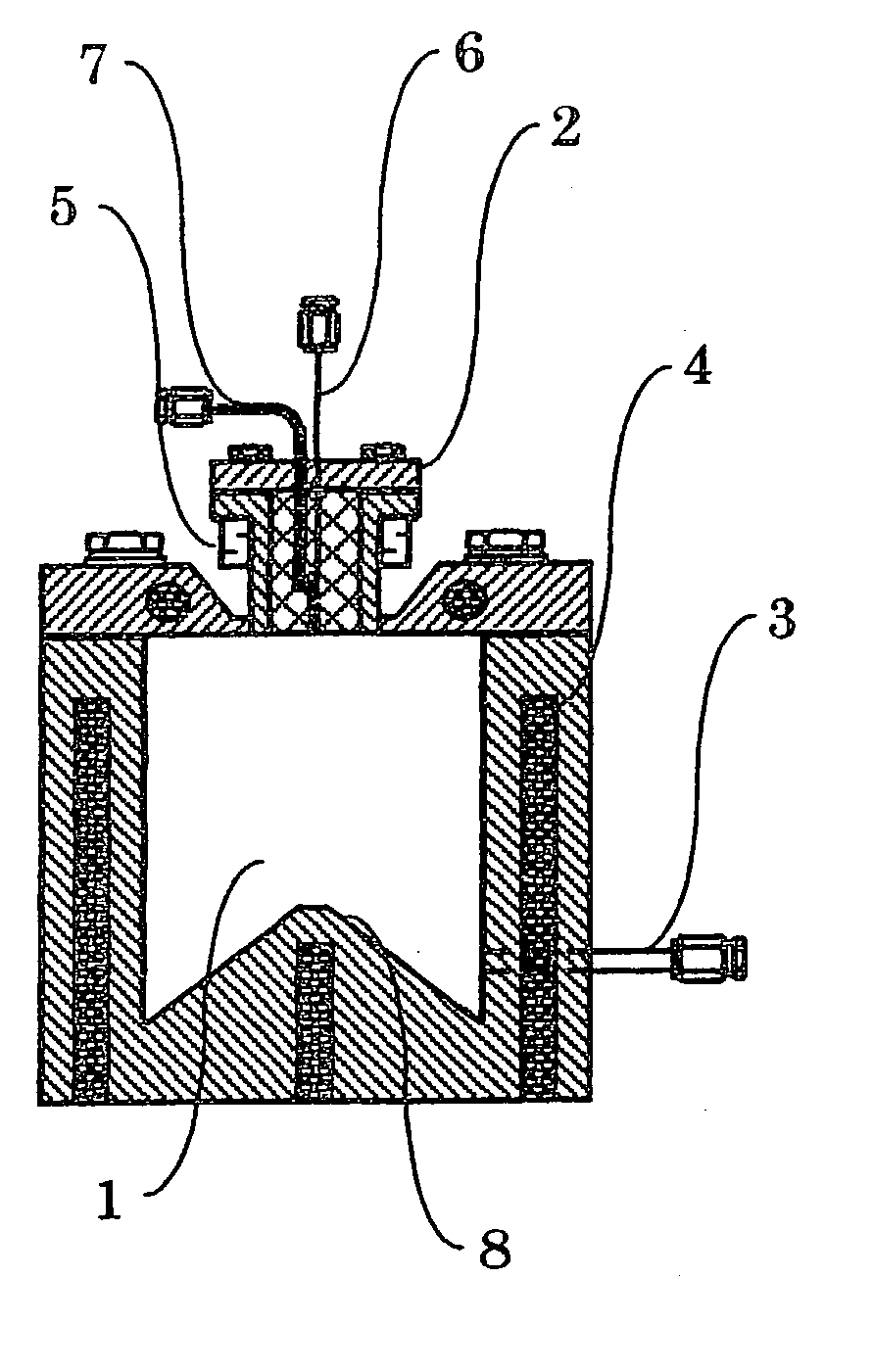
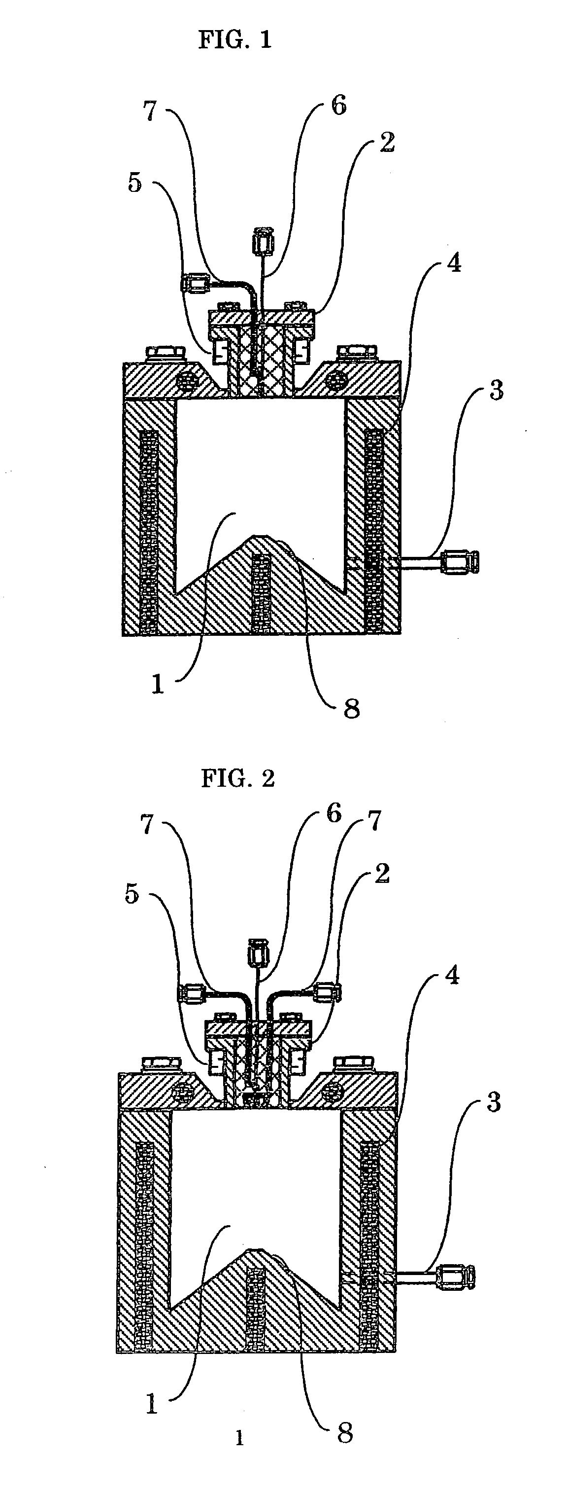
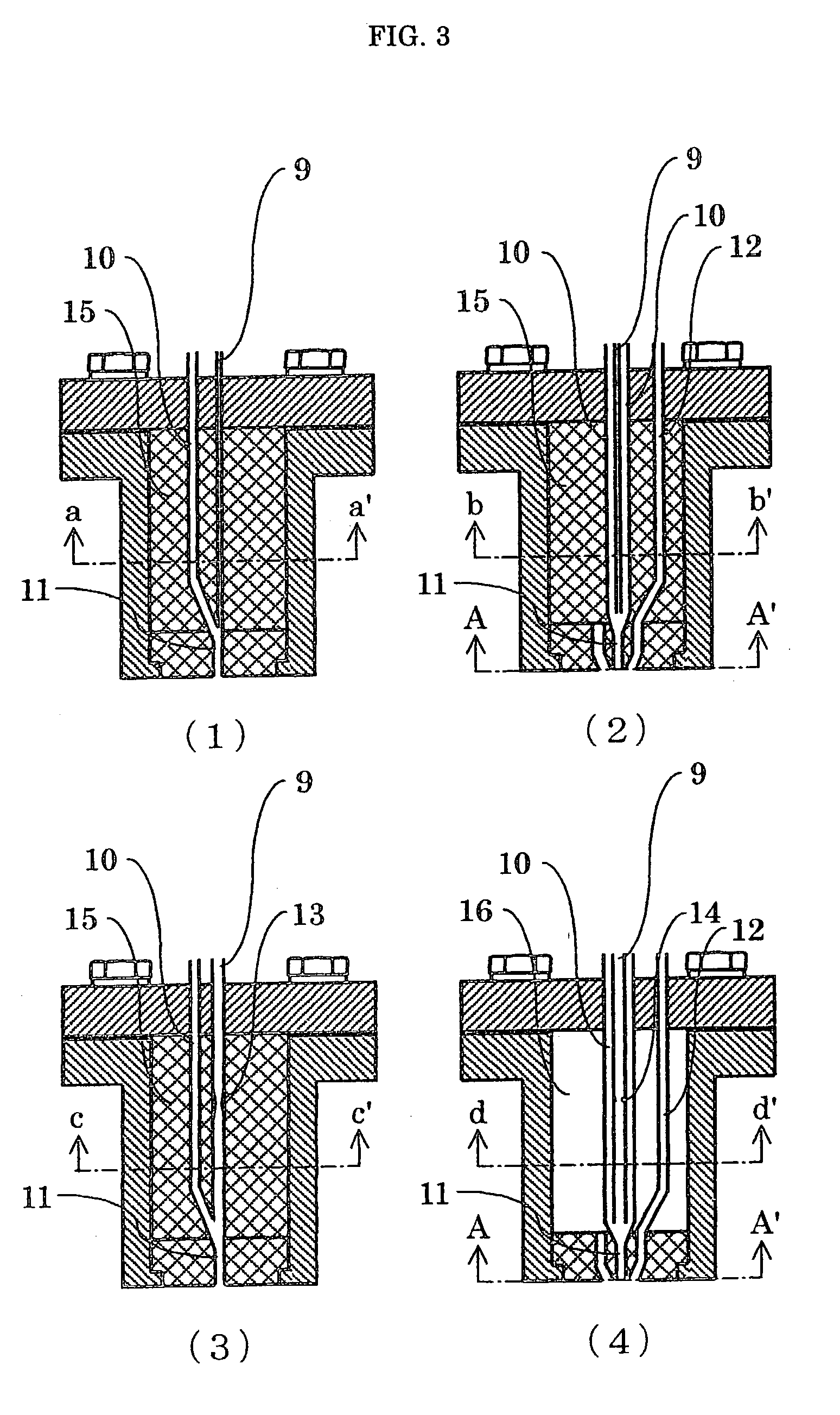
[0044] There was prepared a CVD material feed portion having the passageways as illustrated in FIG. 3 (1) in which the inside thereof was constituted of a fluororesin (PFA), and the portion in contact with the outside of the vaporizer was constituted of stainless steel (SUS316). The PFA made portion was a column having an outside diameter of 16 mm and a height of 34.2 mm. The stainless steel outside the column had a thickness of 2.0 mm. The CVD material feed portion had such constitution that the CVD material passageway and the carrier gas passageway were stainless steel pipes, and the mixing passageway for the CVD material and the carrier gas connected to the vaporization chamber was constituted of a fluororesin (PFA). The CVD material passageway was a capillary having an inside diameter of 0.1 mm, the inside diameters of the carrier gas passageway and the mixing passageway for the CVD material and the carrier gas were 1.8 mm and 0.25 mm respectively. Further, a junction joining th...

example 2

[0047] Example 2 was conducted by the use of the same apparatus for vaporizing and supplying as employed in Example 1 and a liquid CVD material having a concentration of 0.3 mol / liter in which Pb(DPM).sub.2 as a solid CVD material dissolved in tetrahydrofuran (THF) as a solvent was vaporized and supplied in the following manner. The vaporization chamber was set on 1.3 kPa (10 torr) and at the temperature of 210.degree. C., and by feeding the CVD material with a flow rate of 0.36 g / min and argon gas with a flow rate of 300 milliliter / min, the liquid CVD material was vaporized in the chamber. During the foregoing process, cooling water was supplied to maintain the temperature of the stainless steel of the a CVD material feed portion at 30.+-.2.degree. C.

[0048] After continuous test for vaporizing and supplying for ten hours, the amount of the adhesion of the solid CVD material, both the pressure fluctuation in the vaporization chamber and the flow rate fluctuation in the liquid mass f...

example 3

[0049] Example 3 was conducted by the use of the same apparatus for vaporizing and supplying as employed in Example 1 and a liquid CVD material having a concentration of 0.3 mol / liter in which Ti(OiPr).sub.2(DPM).sub.2 as a solid CVD material was dissolved in tetrahydrofuran (THF) as a solvent was vaporized and supplied in the following manner. The vaporization chamber was set on 1.3 kPa (10 torr) and at the temperature of 230.degree. C., and by feeding the CVD material with a flow rate of 0.2 g / min and argon gas with a flow rate of 100 milliliter / min, the liquid CVD material was vaporized in the chamber. During the foregoing process, cooling water was supplied to maintain the temperature of the stainless steel of the a CVD material feed portion at 30.+-.2.degree. C.

[0050] After continuous test for vaporizing and supplying for ten hours, the amount of the adhesion of the solid CVD material, both the pressure fluctuation in the vaporization chamber and the flow rate fluctuation in th...


PUM

PropertyMeasurementUnit
inner diameteraaaaaaaaaa
lengthaaaaaaaaaa
diametersaaaaaaaaaa

Abstract

The present invention provides a vaporizer comprising a vaporization chamber for a CVD material, a CVD material feed portion supplying the CVD material for the vaporization chamber, a vaporized gas exhaust port and a heating means for heating the vaporization chamber, characterized in that the CVD material feed portion has passageways for the CVD material and for a carrier gas respectively and the passageway for the CVD material has a pressure loss-inducing means for the CVD material. At the same time, the present invention provides an apparatus for vaporizing and supplying that feeds a CVD material to a vaporizer via a liquid flow controller, and after vaporizing the CVD material that supplies the vaporized gas for a semiconductor production apparatus, characterized in having a pressure loss-inducing means for the CVD material between the liquid flow controller and the vaporizer. According to the present invention, even in the case of vaporizing and supplying with a decrease in a feed amount of a carrier gas to be supplied accompanying the CVD material employing a solid CVD material, reducing and stabilizing both the pressure fluctuation in the vaporizer and the flow rate fluctuation in the liquid flow controller and efficiently vaporizing a CVD material at a desirable concentration and flow rate without causing deposit or adhesion of the solid material in the vaporization chamber can be achieved.

Description

[0001] The present invention relates to a vaporizer and an apparatus for vaporizing and supplying that are employed for supplying a gaseous CVD material for a chemical vapor deposition (CVD) apparatus used in the manufacture of a semiconductor and the like. More particularly, it pertains to a vaporizer and an apparatus for vaporizing and supplying that are employed for supplying a liquid CVD material or a solution of a liquid CVD material of a solid CVD material in a solvent each at desirable concentration and flow rate in high efficiency for the apparatus used in the manufacture of a semiconductor.[0002] Recently in the field of semi-conductors, a lead titanate zirconate (PZT) film, a barium strontium titanate (BST) film, a tantalic acid strontium bismuth (SBT) film, a titanic acid zirconate lantern lead (PLZT) film, etc., each having a high dielectric constant and also a high step coverage has been used as an oxide-based dielectric film for a semiconductor memory. In regard to the...

Claims


Application Information

Patent Timeline
Patent Type & Authority Applications(United States)
IPC IPC(8): C23C16/448H01L21/205
CPCY10S261/65C23C16/4485H01L21/205
Inventor TAKAMATSU, YUKICHITONARI, KAZUAKIIWATA, MITSUHIROKIRIYAMA, KOJIASANO, AKIRA
Owner JAPAN PIONICS
Why Eureka
Try Eureka