Method and apparatus for active power factor correction with minimum input current distortion

a technology of active power factor and input current, which is applied in the direction of electric variable regulation, process and machine control, instruments, etc., can solve the problems of low power transmission efficiency, undesirable line voltage shape distortion, and possible interference with other units connected to the power lin

Inactive Publication Date: 2003-12-04
GREEN POWER TECH LTD
View PDF0 Cites 141 Cited by
  • Summary
  • Abstract
  • Description
  • Claims
  • Application Information

AI Technical Summary

Problems solved by technology

Injection of high harmonics into the power line and poor power factor in general, is known to cause many problems.
Among these are the lower efficiency of power transmission, possible interference to other units connected to the power line, and distortion of the line voltage shape that is undesirable.
Consequently, the rms current will limit the maximum power that can be drawn from the line.
Cost is of great concern considering the fact that the APFC is an add-on expense to the functionality of the original equipment in which the APFC stage is included.
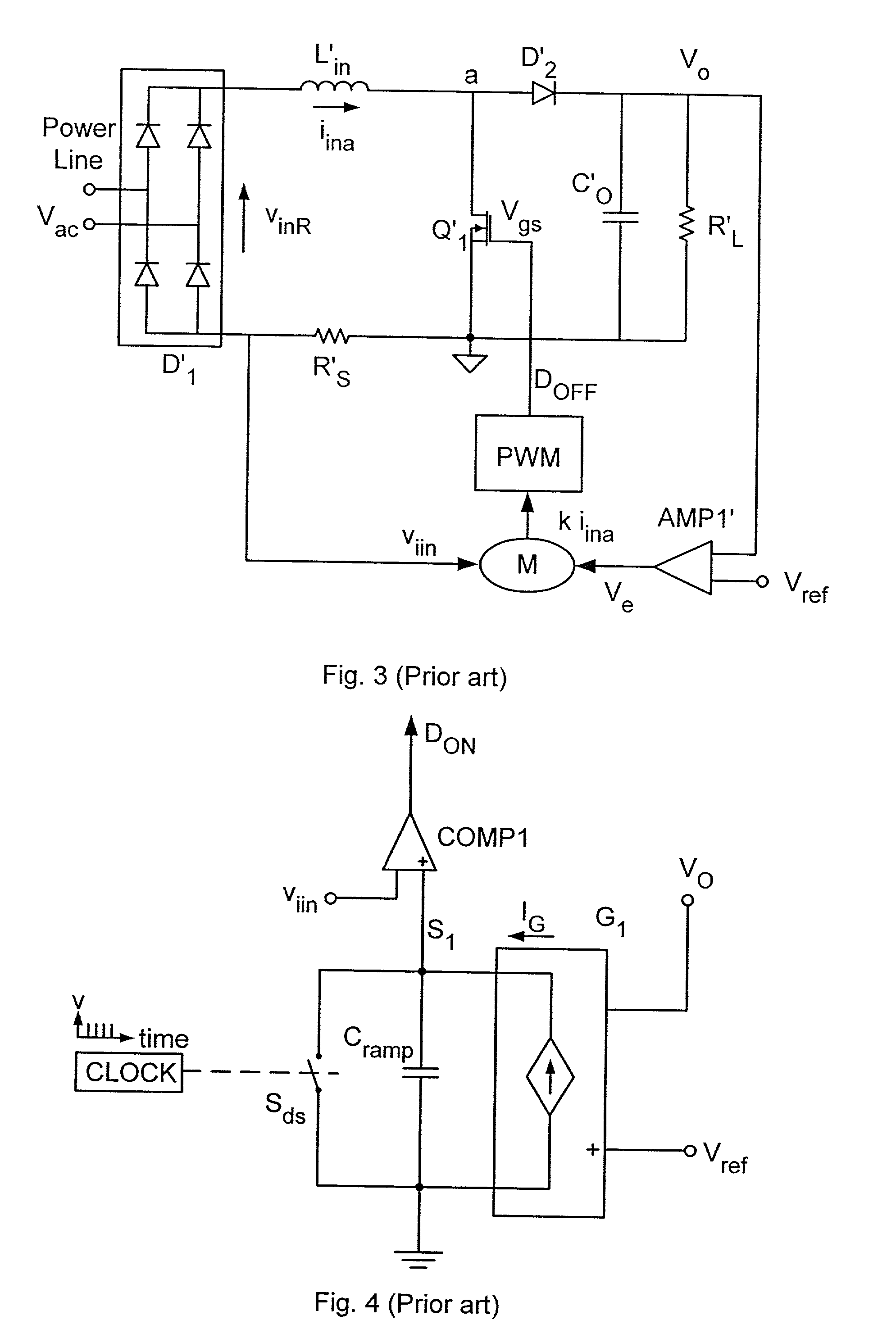
A major drawback of the prior art implementation of the APFC is the need for sensing the input voltage V.sub.inR, namely the line voltage after rectification.
Due to the switching effects, the input voltage is normally noisy and is susceptible to interference pick-up that may distort the reference signal and hence the input current.
However, prior art methods that do not sense the input voltage suffer from a number of drawbacks that deteriorate their performance, in particular resulting in a higher Total Harmonic Distortion (THD).
Furthermore, these prior art methods do not include means to ensure soft switching of the main switch.
This deficiency is a major drawback in high power applications, where the reverse recovery current of the main diode may cause substantial power losses and high stresses on the main diode and switch.
As pointed out above, the prior art realization of APFC systems with no sensing of input voltage suffer from a number of drawbacks that lead to inferior performance.
A major problem that causes an increase in the undesired input current harmonics, is the modulation of the duty cycle by the ripple of the output voltage.
However this will result in large undesired overshoots and undershoots in the output voltage in response to load changes.
Another drawback of the prior art solutions is the distortion of the input current due to errors in the realization of the basic relationship given by eq.
Another drawback of the prior art solutions using APFC systems without input voltage sensing is the hard switching of the main switch at "turn-on".
The above examples show that the prior art solutions to an APFC stage that does not require the sensing of the input voltage have considerable practical drawbacks.
This could be a limitation in some applications when the line voltage is high.
In practice, due to offsets of amplifiers, leakage current of transistors, etc., SLOPE may lock to a minimum level.
Consequently the system will be unable to produce the correct duty cycle as dictated by the output to input voltage ratio (Vo / v.sub.inR).
A resulting non-desired duty cycle t.sub.ona might be too large as compared to a desired one t.sub.ond, and consequently the input current will increase to a too high level.
This addition could be significant at light load.
However, line harmonic limitation recommendations and standards such as IEC1000-3-2 exempt equipment from complying with the standard at light loads.
Consequently, the added distortion at light load is unimportant.
This will cause a current build-up in the inductor, with a possible catastrophic consequence.
In some cases, the required value of the capacitor may be too large for implementation on chip--when a microelectronics solution is desired.
Another practical problem that may deteriorate the performance of an APFC system, built according to this invention, is the interference due to spikes that are typical of a switch mode system.
The spikes may cause false trigger of the comparators used in the analog implementation described above.

Method used


Image

  • Method and apparatus for active power factor correction with minimum input current distortion
  • Method and apparatus for active power factor correction with minimum input current distortion
  • Method and apparatus for active power factor correction with minimum input current distortion

Examples


Embodiment Construction

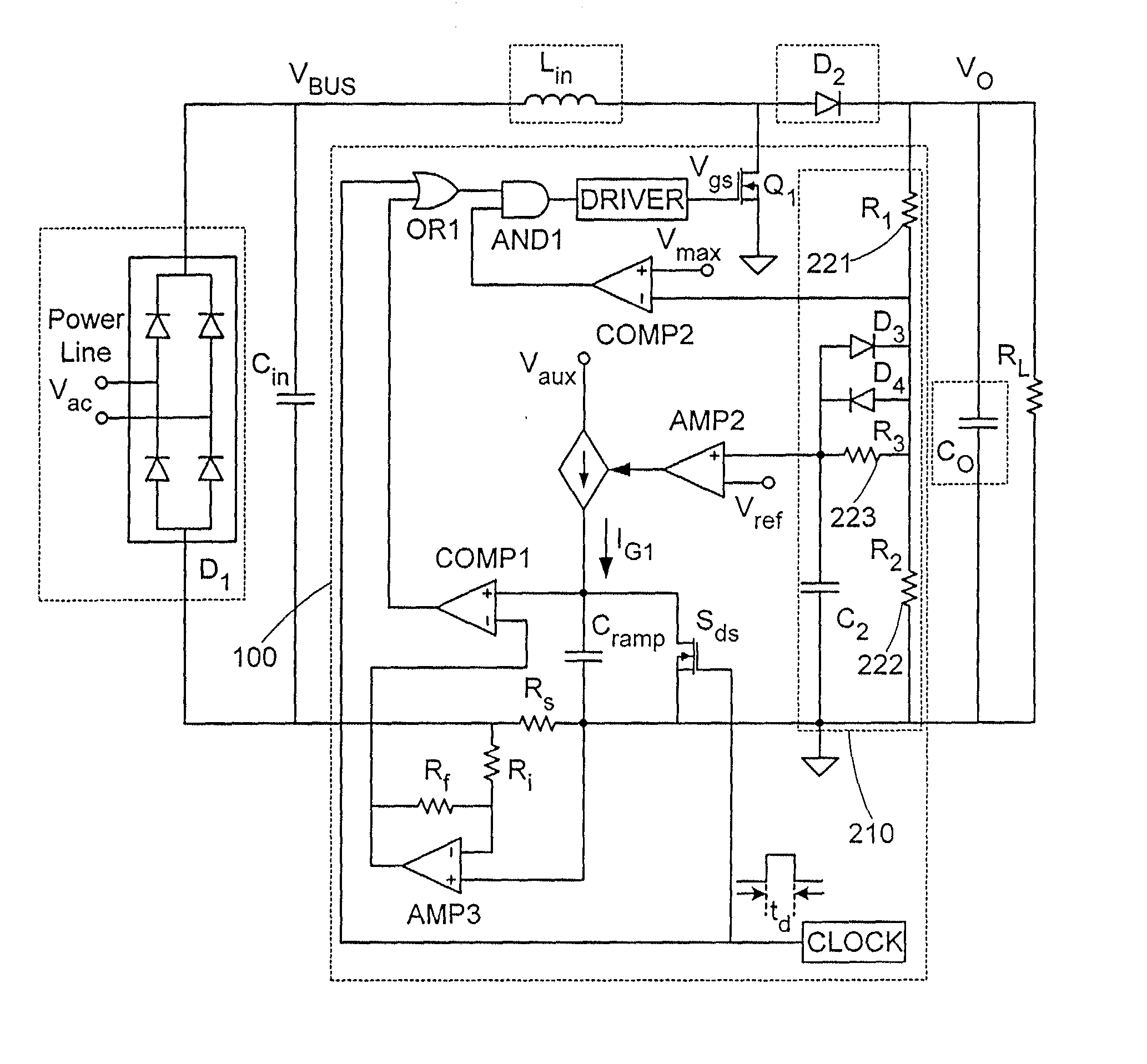
[0074] An example of a preferably practical embodiment of an APFC stage according to this invention is shown in FIG. 19. This circuit diagram consists of a power stage 500 with a snubber, a driver 504, a ramp generator 506, a current amplifier 508, a feedback 510, a D.sub.ON blanking 512 and a PWM logic circuitry 514. Power stage 500 (boost topology) includes a main switch Q.sub.3, and output diode D.sub.10, an input inductor L.sub.in, a current sense resistor R.sub.29, and a snubber circuitry 528 (comprised of diodes D.sub.13 and D.sub.14, a capacitor C.sub.6, and an inductor L.sub.sn). The gate of Q.sub.3 is controlled by a driver 504 that is based on two MOSFET transistors Q.sub.6 and Q.sub.8. The input current of the power stage is sensed by sense resistor R.sub.29, amplified by a current error amplifier U.sub.5B and filtered out by a low pass filter 542 (which includes a resistor R.sub.37 and a capacitor C.sub.13). The offset signal needed to handle the low load situation is im...


PUM


Abstract

A method for reducing the harmonics contents of an input current drawn from a power line into an electrical system without sensing an input voltage, the method comprising providing an active power factor correction controller with a switch module having a main switch and a timing device, wherein the main switch has an on-time correlated with an on-duty cycle duration, and an off-time correlated with an off-duty cycle duration, and maintaining a linear relationship between the off-duty cycle duration and the input current by using the timing device; and an apparatus for active power factor correction with minimum input current distortion, comprising an active power factor correction assembly that includes a main switch and a timing device, wherein the main switch has associated therewith an on-time correlated with an on-duty cycle duration, and an off-time correlated with an off-duty cycle duration, and wherein the timing device generates the mentioned on-time and off-time, and linearization means for maintaining a linear relation between the off-duty cycle duration and the input current.

Description

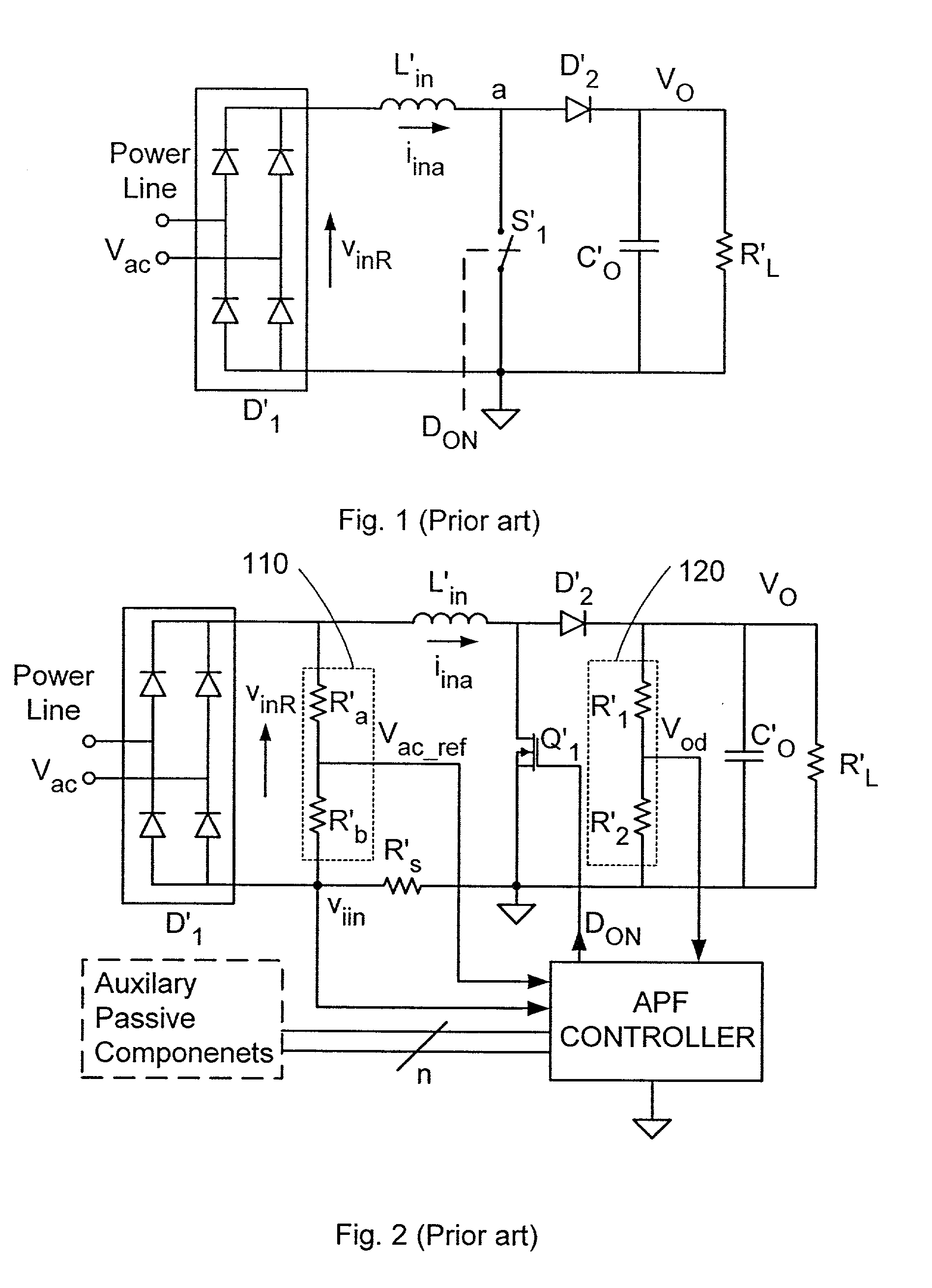
FIELD AND BACKGROUND OF THE INVENTION[0001] The present invention relates to control method and apparatus of modular design for regulating the harmonics contents of the current drawn from the power line by electrical equipment and loads, and in particular to the electronic circuit design, physical construction and layout of such an apparatus.[0002] Switch Mode and Resonant Converters are widely used for DC-DC, DC-AC, AC-DC and AC-AC conversion. In some groups of applications, the purpose of the power conversion scheme is to shape the input current seen at the input of the converter. For example, in an input power stage known in the art as an Active Power Factor Correction (APFC) circuit, the function of the converter is to ensure that the AC current seen by the power line is in phase with the line voltage with minimum high order harmonics. A typical well-known embodiment of APFC is shown in FIG. 1. In this method, the input voltage is rectified by a diode bridge D'.sub.1 and fed to ...

Claims


Application Information

Patent Timeline
Patent Type & Authority Applications(United States)
IPC IPC(8): H02M1/00H02M1/42
CPCY02B70/126H02M1/4225Y02B70/10Y02P80/10
Inventor BEN-YAAKOV, SHMUELZELTSER, ILYA
Owner GREEN POWER TECH LTD
Why Eureka
Try Eureka