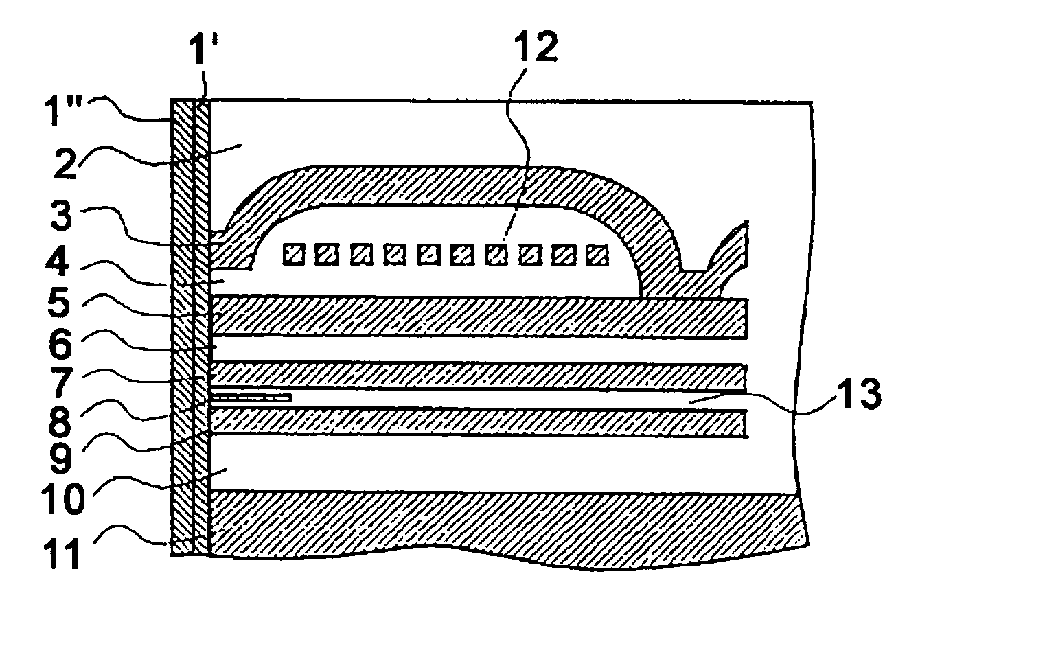
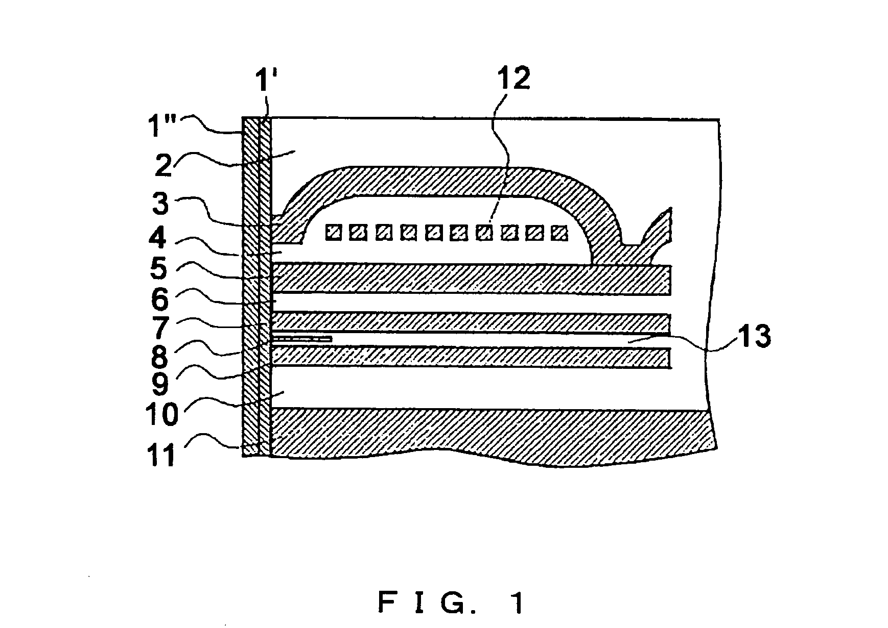
Thin-film magnetic head, method for producing the same and magnetic disk device using the same
a thin-film magnetic head and magnetic disk technology, applied in the field of magnetic recording, can solve the problems of poor coherence or adhesiveness between the thin-film magnetic head and the protective film, poor film strength, and peeling of the film
- Summary
- Abstract
- Description
- Claims
- Application Information
AI Technical Summary
Benefits of technology
Problems solved by technology
Method used
Image

Examples
examples
Examples: Formation of the Protective Film
[0072] Formation of a film as the lower layer--method 1 (plasma CVD method) (Sample 1) Si(CH.sub.3).sub.4 and C.sub.2 H.sub.4 were introduced as material gases for compounds containing Si, C and H, at the flow rates of 8 SCCM and 20 SCCM respectively. RF of 500 W was applied as an alternating current for generating plasma, and the operating pressure of 6.66 Pa and the self-bias of -400 V were applied on the running surface of the MR thin-film magnetic head, thereby forming a film of 5 .ANG..
[0073] (Sample 2) Si(CH.sub.3).sub.4 and C.sub.2H.sub.4 were introduced as material gases for compounds containing Si, C and H, at the flow rates of 10 SCCM and 30 SCCM respectively. RF of 500 W was applied as an alternating current for generating plasma, and the operating pressure of 6.66 Pa and the self-bias of -400 V were applied on the running surface of the MR thin-film magnetic head, thereby forming a film of 10 .ANG..
[0074] (Sample 3) Si(CH.sub.3)....
PUM
| Property | Measurement | Unit |
|---|---|---|
| Thickness | aaaaa | aaaaa |
| Density | aaaaa | aaaaa |
| Electric potential / voltage | aaaaa | aaaaa |
Abstract
Description
Claims
Application Information
 - R&D
- Intellectual Property
- Life Sciences
- Materials
- Tech Scout
- Unparalleled Data Quality
- Higher Quality Content
- 60% Fewer Hallucinations
Browse by: Latest US Patents, China's latest patents, Technical Efficacy Thesaurus, Application Domain, Technology Topic, Popular Technical Reports.
© 2025 PatSnap. All rights reserved.Legal|Privacy policy|Modern Slavery Act Transparency Statement|Sitemap|About US| Contact US: help@patsnap.com