Magneto-resistance effect element, magnetic memory and magnetic head

a technology of magneto-resistance and effect elements, applied in the field of magneto-resistance effect elements, magnetic memory and magnetic head, can solve the problems of inability to reduce cells to the size, inability to achieve mass storage, and large power consumption

Inactive Publication Date: 2004-05-27
KK TOSHIBA
View PDF9 Cites 61 Cited by
  • Summary
  • Abstract
  • Description
  • Claims
  • Application Information

AI Technical Summary

Problems solved by technology

However, regarding a cell size of the memory, when an architecture where a cell is constituted by one transistor and one TMR element is used, there occurs such a problem that the cell can not be reduced down to the size of a DRAM (Dynamic Random Access Memory) of a semiconductor device or smaller.
However, in the both cases, since reversal is conducted with a current magnetic field due to current pulses at a writing time into a storage layer, power consumption is large.
Further, since an allowable current density in a wire when a mass storage is to be achieved is limited, the mass storage can not be achieved.
There occurs such a problem that the memory becomes large in chip size, as compared with another non-volatile solid magnetic memory, for example, a ferroelectric random access memory using a ferrodielectric material capacitor, a flush memory or the like, so that a competitive power of the memory is lost.
However, even if these magnetic storage devices are used, it has been much difficult to suppress the writing current value to 1 mA or less.
Further, storage layers (magnetization free layer) of a ferromagnetic tunneling junction which have been conventionally proposed are usually determined according to their volumes defined at a time of junction separation, and there occurs a problem about thermal stability when the design rule becomes 0.25 .mu.m or less.
However, when a structure of the multi-layered film disclosed in U.S. Pat. No. 5,953,248 is employed, such a problem arises that a multi-hysteresis occurs and an MR change rate lowers.

Method used


Image

  • Magneto-resistance effect element, magnetic memory and magnetic head
  • Magneto-resistance effect element, magnetic memory and magnetic head
  • Magneto-resistance effect element, magnetic memory and magnetic head

Examples


third embodiment

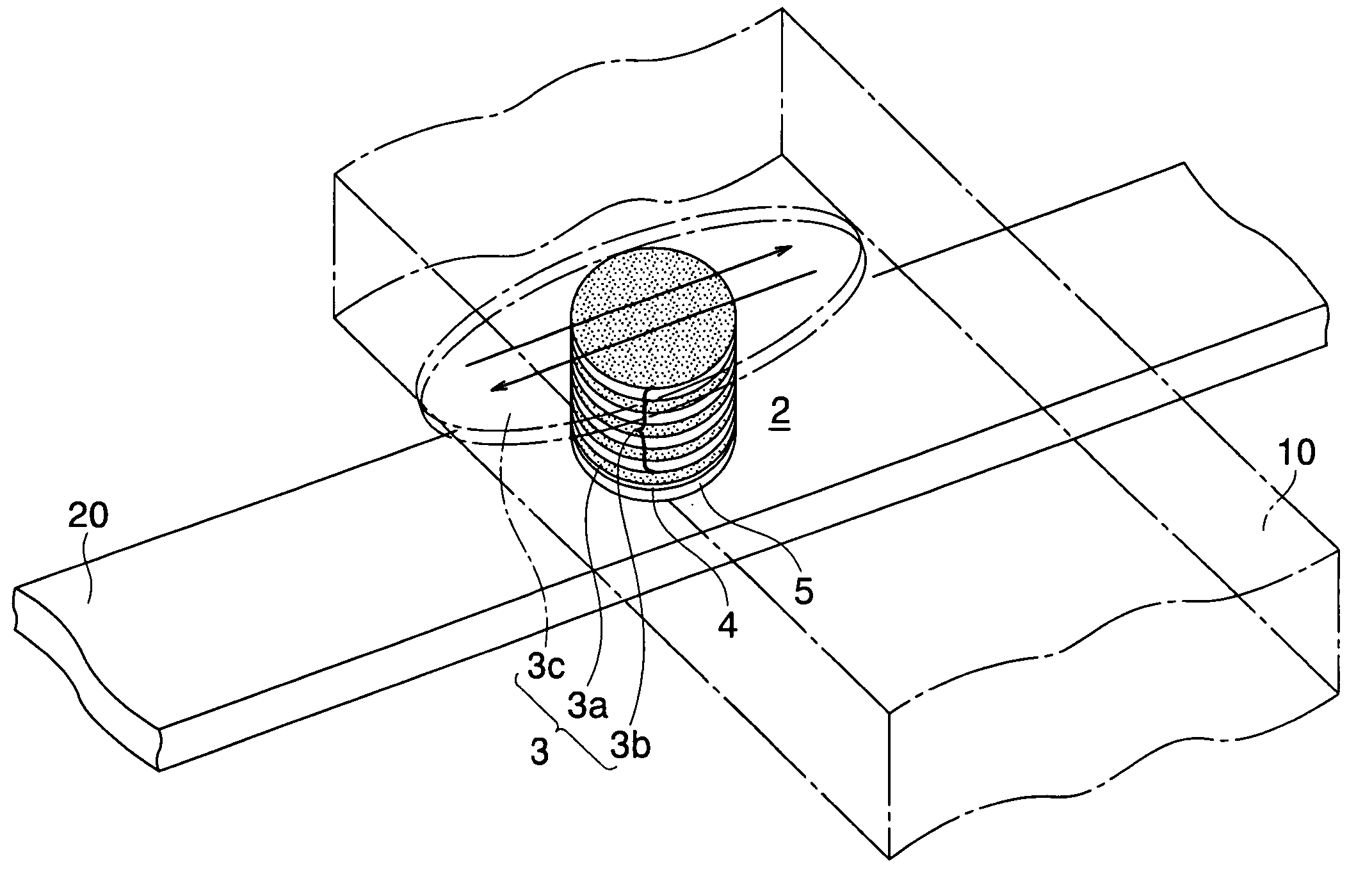
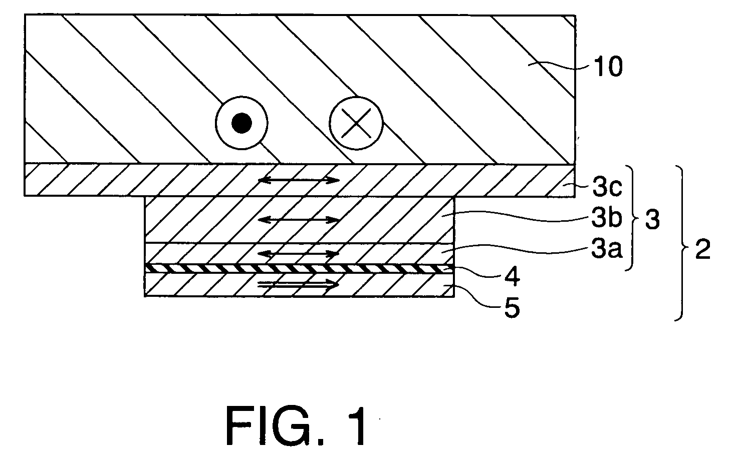
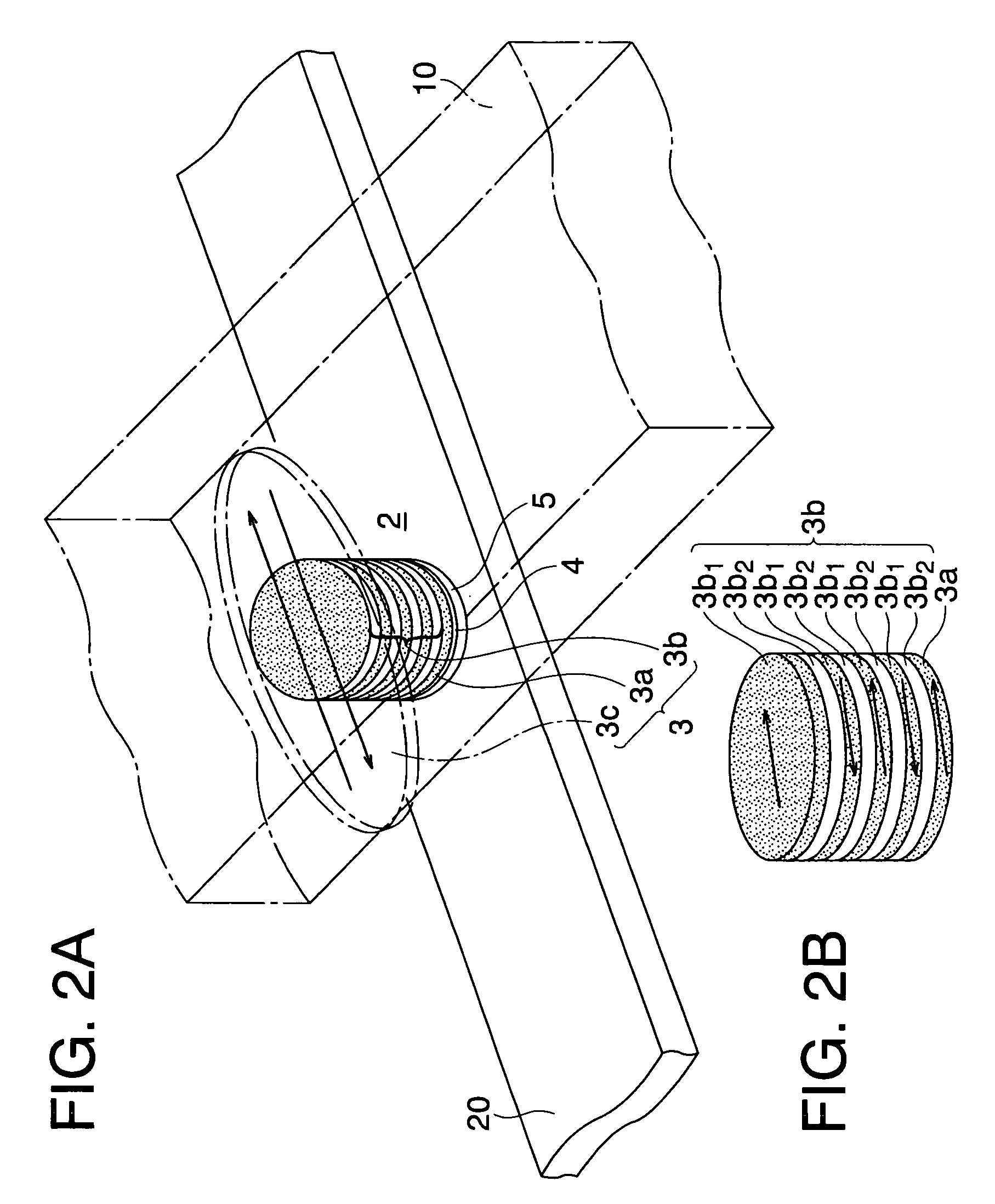
[0107] Next, a magnetic memory according to a third embodiment of the present invention will be explained with reference to FIGS. 15A and 15B. FIG. 15A is a view showing a structure of a unit memory cell of a magnetic memory according to this embodiment and FIG. 15B is a sectional view of the unit memory cell taken along line A-A shown in FIG. 15A. A magnetic memory according to this embodiment is constituted such that the yoke 8 provided on the bit line BL also extends on side portions of the bit line BL shown in FIGS. 14A and 14B in the magnetic memory according to the second embodiment shown in FIGS. 14A and 14B. Thereby, a writing current can be further reduced as compared with that in the second embodiment. Incidentally, the T-shaped magnetization free layer of the TMR element 2 and the yoke are not connected to each other, and a magnetic interaction therebetween does not occur while no current flows in the bit line BL.

[0108] The magnetic memory according to this embodiment of ...

fourth embodiment

[0109] Next, a magnetic memory according to a fourth embodiment will be explained with reference to FIGS. 16A and 16B. FIG. 16A is a sectional view showing a structure of a unit memory cell in a magnetic memory according to this embodiment, and FIG. 16B is a sectional view of the unit memory cell taken along line A-A shown in FIG. 16A. A magnetic memory according to this embodiment is constituted such that the T-shaped magnetization free layer constituting the TMR element 2 is provided adjacent to the word line WL instead of the bit line BL and an opposed end portion of the TMR element 2 from the T-shaped magnetization free layer is connected to the source region 18a of the reading cell selecting transistor 18 via the leading electrode 12 and the connection plug 14 in the magnetic memory in the second embodiment. A bit line BL is disposed above the leading electrode 12 via an insulating film (not shown). A yoke 8 is provided on the bit line BL so as to extend to side portions of the...

fifth embodiment

[0112] Next, a magnetic memory according to a fifth embodiment of the present invention will be explained with reference to FIGS. 17A, 17B and 17C. FIG. 17A is a sectional view showing a structure of a magnetic memory according to this embodiment, FIG. 17B is a view showing a structure of a unit memory cell of the magnetic memory according to this embodiment, and FIG. 17C is a sectional view of the unit memory cell taken along line A-A shown in FIG. 17B.

[0113] A magnetic memory according to this embodiment has a structure that TMR elements 2 are respectively connected to a reading / writing bit line BL in a parallel manner via diodes 9. Incidentally, the TMR element used in this embodiment is either one of the TMR elements of the first embodiment and its modifications. The other ends of the respective TMR elements 2 are connected with reading / writing word lines WL. Incidentally, the T-shaped magnetization free layer constituting the TMR element 2 is provided adjacent to the word line ...


PUM

PropertyMeasurementUnit
aspect ratioaaaaaaaaaa
thicknessaaaaaaaaaa
currentaaaaaaaaaa

Abstract

The magneto-resistance effect element includes: a first ferromagnetic layer serving as a magnetization fixed layer; a magnetization free layer including a second ferromagnetic layer provided on one side of the first ferromagnetic layer, a third ferromagnetic layer which is formed on an opposite side of the second ferromagnetic layer from the first ferromagnetic layer and has a film face having an area larger than that of the second ferromagnetic layer and whose magnetization direction is changeable by an external magnetic field, and an intermediate layer which is provided between the second ferromagnetic layer and the third ferromagnetic layer and which transmits a change of magnetization direction of the third ferromagnetic layer to the second ferromagnetic layer; and a tunnel barrier layer provided between the first ferromagnetic layer and the second ferromagnetic layer.

Description

[0001] This application is based upon and claims the benefit of priority from prior Japanese Patent Application No. 2002-339934, filed on Nov. 22, 2002 in Japan, the entire contents of which are incorporated herein by reference.[0002] The present invention relates to a magneto-resistance effect element, a magnetic memory and a magnetic head.RELATED ART[0003] A magneto-resistance effect element having magnetic films is used for a magnetic head, a magnetic sensor and so forth, and it has been proposed to be used for a solid magnetic memory. In particular, there is an increasing interest in a magnetic random access memory (hereinafter, referred to as "MRAM (Magnetic Random Access Memory)), which utilizes the magneto-resistance effect of ferromagnetic material, as a next generation solid non-volatile memory capable of carrying out a rapid reading / writing and an operation with large capacity and low power consumption.[0004] In recent years, a ferromagnetic tunnel junction element or the ...

Claims


Application Information

Patent Timeline
Patent Type & Authority Applications(United States)
IPC IPC(8): G11C8/02H01L27/105G11C11/155G11C11/16H01F10/32H01L21/8246H01L27/22H01L43/08
CPCB82Y10/00B82Y25/00G11C11/16H01L43/08H01F10/3272H01L27/224H01L27/228H01F10/3254H10B61/10H10B61/22H10N50/10
Inventor SAITO, YOSHIAKINISHIYAMA, KATSUYATAKAHASHI, SHIGEKI
Owner KK TOSHIBA
Why Eureka
Try Eureka