Components for nano-scale Reactor

a nano-scale reactor and component technology, applied in the field of microfluidics, can solve the problems of complex manufacturing process, general restriction on the type of processing type acceptable, and complex packaging of said devices, and achieve the effects of reducing the evaporation rate of solvent, reducing the cross-section area, and reducing the intensity of electric field

Inactive Publication Date: 2004-06-17
TOUZOV IGOR
View PDF74 Cites 42 Cited by
  • Summary
  • Abstract
  • Description
  • Claims
  • Application Information

AI Technical Summary

Benefits of technology

0073] Intake area occupied by the droplet encounter redistribution of electric carriers and reduction or complete compensation of intense electric field at 510 locations. This prevents accidental capture of second droplet by the same intake area.
0074] The storage apparatus with multiple dispensing parts is shown on FIG. 6. The liquid occupies space in segments 601 due to decreasing cross-section area of cavity 602 along the passes from the intake part 603 to the dispensing channels 604. M...

Problems solved by technology

Drawbacks of said methods include complex packaging of said devices that is handling tasks of interconnections of external electric and pneumatic/hydraulic lines, and complex manufacturing process that might require creation of complex 3D arrays of electrodes and/or electrical elements.
This phenomenon imposes general restriction on types of acceptable processing types.
Majority of disclosed techniques restrict processing of micro volumes to enclosed systems and dispenser type devices.
Major drawbacks of prior art methods comprise limited ability to control amount of compounds deposited on said stamp.
Disclosed device does not have fixed means to guarantee equivalence of all produced micro volumes and relies on controlling means of electroosmotic propulsion.
This approach has significant speed restrictions, since droplets formation can only occurs at ...

Method used


Image

  • Components for nano-scale Reactor
  • Components for nano-scale Reactor
  • Components for nano-scale Reactor

Examples


example 2

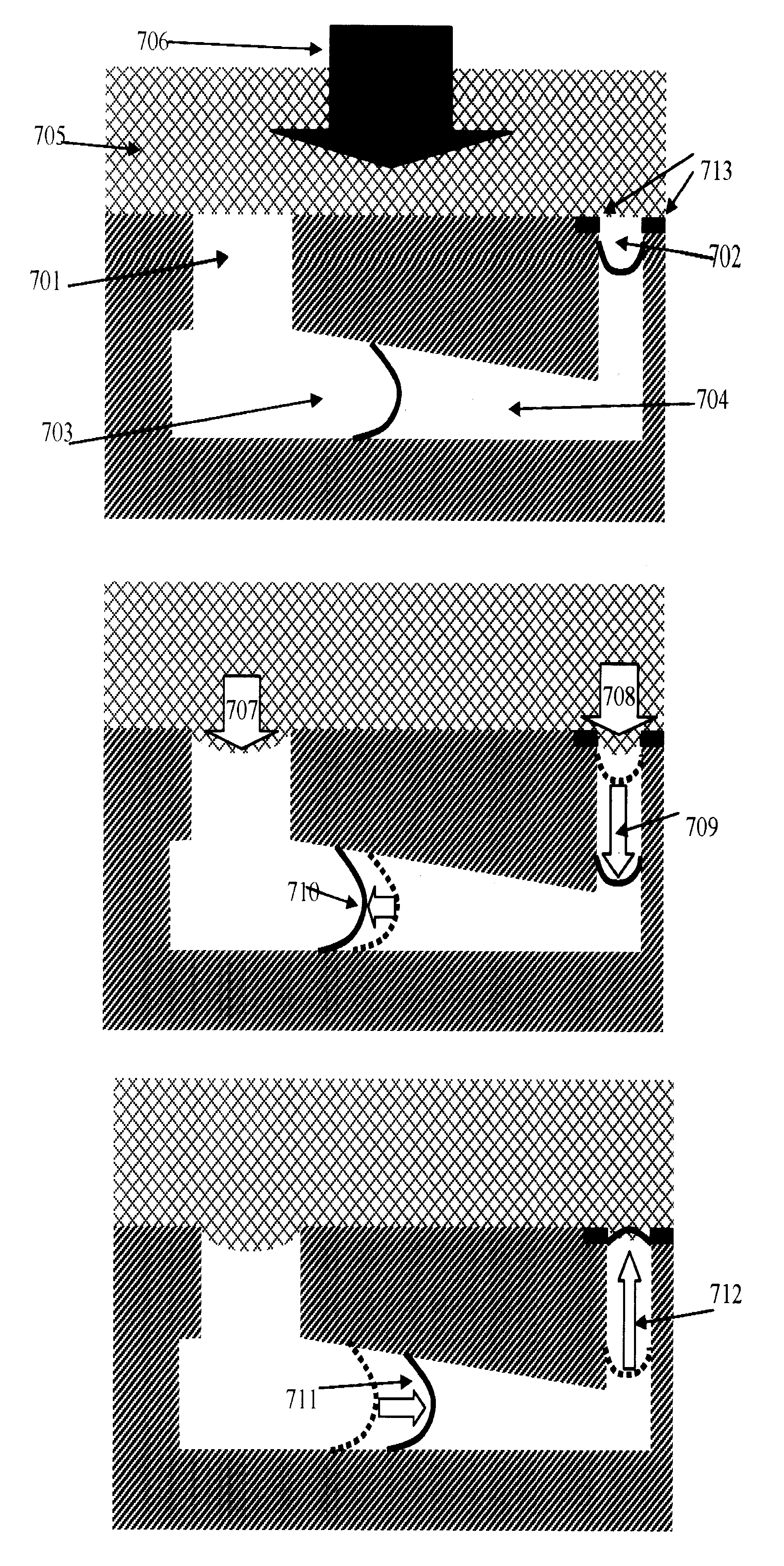
[0078] FIG. 18 illustrates yet another design of microfluidic storage device that employs array of microfluidic storage devices. This array manufactured using process described in previous example. On dispensing surface of the plate plurality of groves were created using etching or micromachining processes. These groves then filled with porous hydrophilic material 1803 (silicon oxide in this example). On top of this thin layer of hydrophobic material 1804 (sputtering of aluminum can be used) was deposited using photo mask to preserve plurality of open segments 1805.

[0079] Operation of this device are identical to one described in the previous example, except that volume of porous material 1803 is saturated with water. This design creates artificial area with high vapor pressure around open ports and contains significant supply of liquid solvent. In this example total volume of adsorbed water is 1 milliliter, and dry out time for the array is increased to 36 hours.

[0080] This storage...

example 3

[0083] This example describes devices identical to ones disclosed in previous two examples with one exceptional feature. These devices do not contain dedicated intake port, but rather singe port and intake area surrounding it. Materials and manufacturing process for these devices remain unchanged from previous two samples, but method of their use changes.

[0084] Said devices are disposed in atmosphere of helium and special steps could be taken to desorb residual gases or other weekly adsorbed liquids from devices. Liquid is then disposed on available ports and device is removed from helium environment.

[0085] Considering dimensions of the example 1, helium diffuses away from said cavity and liquid is completely pooled inside the cavity in less then 15 seconds.

[0086] Micro-Contact Liquid Dispenser

[0087] Apparatus has a flat planar surface with several channels. At least one channel has a cross-section area distinct from others. Channels are connected inside the body of the apparatus. S...

example 4

[0109] Device on FIG. 13 has polystyrene walls (contact angle 840) 1001 and 1002. Cavity 1003 has FEP walls (contact angle 1110). Diameter of part 1001 is 0.4 micrometer and diameter of part 1002 is 0.2 micrometer. Thickness of cavity 1003 is 0.2 micrometer in the center and 0.25 micrometer total. Gas pressure in volume 1002 is 10 KPa. Liquid 1301 is water at temperature 300 K.

[0110] Differential pressure required for liquid to pass cavity 1003 is 0.5 MPa. This pressure creates meniscus 1304 with curvature radius 1.9 microns and meniscus 1305 with curvature radius 0.28 microns. Formation of micro droplet 1302 allocates 3.4 attoliters and has 14.5 microns curvature radius of lower surface 1303. This significant reduction of pressure in volume 1307 causes redistribution of liquid from area 1306 that results in formation of meniscus 1308.


PUM

PropertyMeasurementUnit
Lengthaaaaaaaaaa
Fractionaaaaaaaaaa
Fractionaaaaaaaaaa

Abstract

Microfluidic devices and methods for operations on micro through nano-meter scales. Methods of processing, handling and analysis of yocto-liter scale volumes. Methods and devices for single-molecule transports in milli-scale dimensions. Methods of laser propulsion of individual cells and droplets. Methods of packaging and manufacturing of micro and nanofluidic devices. Method of improving dispensing accuracy. Methods of uses and manufacturing of micro-optico-fluidic devices. Bottom up processing method. Ionic particle deflector device. Smart package device and methods for high-throughput synthesis and screening. Methods and devices for controlled refills of micro stamps. Methods and devices for insitu concentration and dilution of micro volumes of solids and liquids. Methods and devices for eliminating undesirable dry outs and evaporation of microscale volumes of fluids.

Description

[0001] This application is a regular application of provisional Patent Application No. 60 / 413,927, filed Sep. 25, 2002 which is hereby incorporated by reference in its entirety for all purposesBACKGROUND OF INVENTION[0002] Current state of the art in area of microfluidics that also includes plurality of assays for high-throughput synthesis and screening accounts for vide spectrum of methods, devices and assays all of which operate with relatively small amounts of liquids. Majority of said methods and devices use electric currents in form of electroosmotic propulsion of said liquids, while nearly as large number of said devices use pneumatic propulsion in form of pressure gradients. Only small number of methods was disclosed that engage different propulsion mechanisms. Method of heater induced propulsion was disclosed in U.S. Pat. No. 6,130,098 that employ variations in surface tension of liquid caused by array of heating elements. All aforementioned propulsion techniques are very ro...

Claims


Application Information

Patent Timeline
IPC IPC(8): B01F5/06B01F13/00B01L3/00B01L3/02
CPCB01F5/061Y10T436/2575B01F13/0008B01F13/0059B01F13/0071B01L3/0262B01L3/5025B01L3/502746B01L3/502784B01L3/50857B01L2200/0652B01L2200/0673B01L2300/0896B01L2300/10B01L2400/0403B01L2400/0406B01L2400/0448B01L2400/046B82Y30/00B01F13/0001B01F25/431B01F33/054B01F33/05B01F33/3021B01F33/30
Inventor TOUZOV, IGOR
Owner TOUZOV IGOR
Why Eureka
Try Eureka