Method for producing upsized frp member

a manufacturing method and large technology, applied in the field of large frp member manufacturing, can solve the problems of difficult observation, inability to perform resin injection at appropriate timing, low frp productivity according to this manufacturing method, etc., and achieve the effect of high-quality frp molded body

Inactive Publication Date: 2004-07-08
TORAY IND INC
View PDF8 Cites 80 Cited by
  • Summary
  • Abstract
  • Description
  • Claims
  • Application Information

AI Technical Summary

Benefits of technology

[0008] Accordingly, an object of the present invention is to provide a method for manufacturing a large FRP member, which has superior mass production capability. According to the method described above, a large FRP sheet member can be manufactured at an inexpensive cost without using expensive equipment and, by virtue of high molding efficiency, can be formed by molding in a relatively short molding cycle even in a small operation area, and non-impregnated portions, voids, and the like are not likely to be formed, thereby manufacturing a FRP having superior quality at an inexpensive cost and with high production yield.

Problems solved by technology

However, in addition to high cost required for the formation and storage of the prepregs, since the molding equipment therefor becomes larger, the productivity of FRP according to this manufacturing method has not been so high.
However, when the flow condition of the resin is observed by an operator as described above, some place may become difficult to be observed when a molded body is large, or the position of a front end of the flowing resin may be misunderstood in some case, and hence a problem may arise in that the injection of the resin cannot be performed at appropriate timing.
Furthermore, when a molded body having high heat resistance is manufactured using the bottom mold and the bagging film described above, since the entire mold is heated to a high temperature, it becomes difficult for an operator to observe the flow of the resin by standing beside the mold, or when molding is performed by using a two-sided mold, the flow condition of the resin cannot be observed at all from outside the mold by an operator even when a molded body is relatively small.
Accordingly, as a result, a problem may arise in that timing of injecting the resin from a plurality of injection ports cannot be determined.
However, by the method described above, there have been problems in that the reliability is low, the probability of mass production is low, and the productivity is low.

Method used


Image

  • Method for producing upsized frp member
  • Method for producing upsized frp member
  • Method for producing upsized frp member

Examples


example 1

[0159] (1) Structure: the entirety having substantially a sandwich structure, a planar plate having a length of approximately 5 m and a width of approximately 3 m, the end portion 100 mm wide along the entire periphery of the plate having a skin structure (assuming a secondary structural member of aircrafts, such as a fairing)

[0160] (2) Structure of a reinforcing fiber base material:

[0161] (2-1) Flat surface portions of the sandwich structure (both top and bottom surfaces);

[0162] "Torayca" bidirectional woven fabric (200 g / m.times.6 plies), manufactured by Toray Industries, Inc.

[0163] (2-2) Web portion of the sandwich structure;

[0164] "Torayca" bidirectional woven fabric (200 g / m.times.8 plies), manufactured by Toray Industries, Inc.

[0165] (2-3) Skin structure portion of the periphery end portion;

[0166] "Torayca" bidirectional woven fabric (300 g / m.times.10 plies), manufactured by Toray Industries, Inc.

[0167] (3) Core material: a polymethacryl imide-made foam core (Rohacell); an exp...

example 2

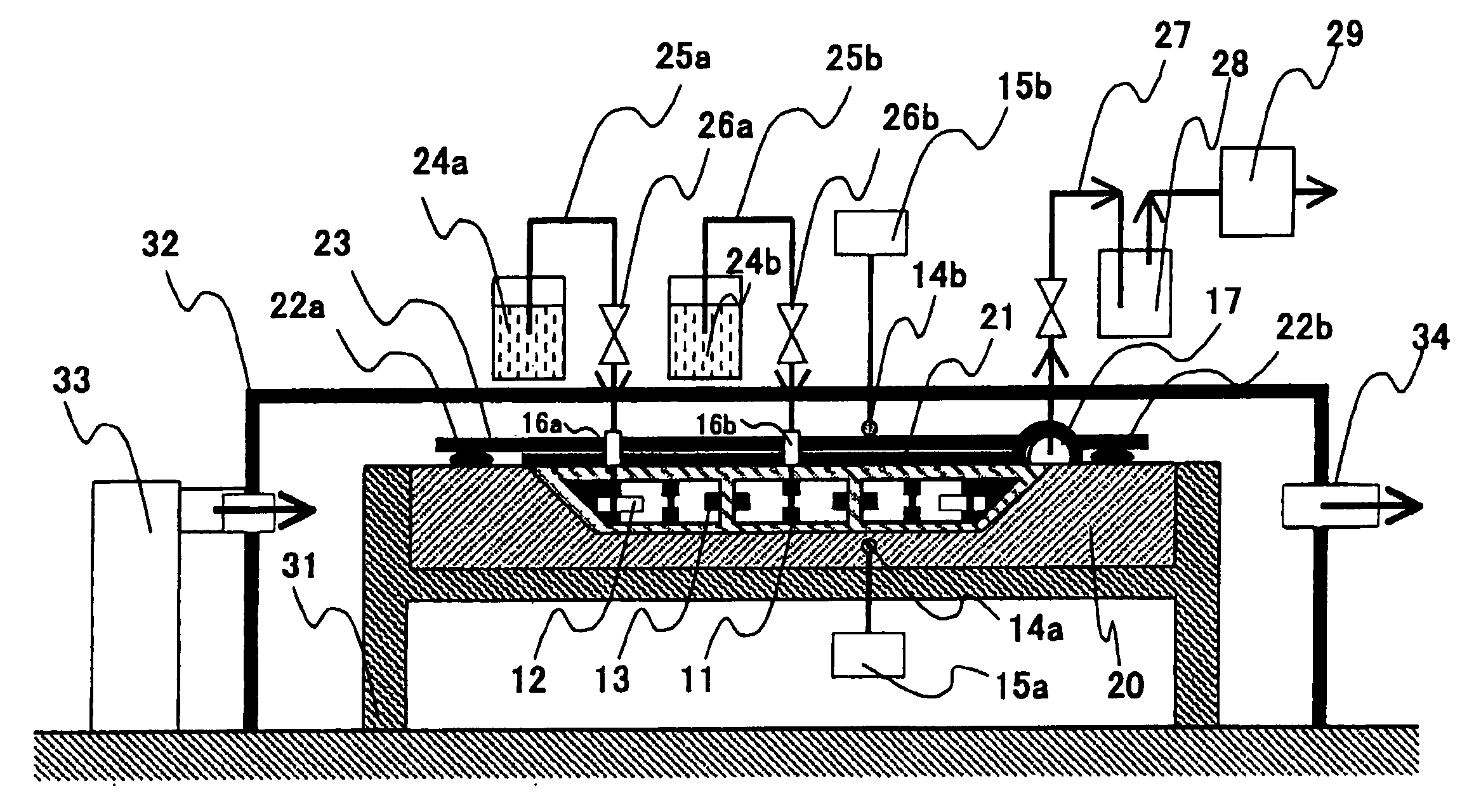
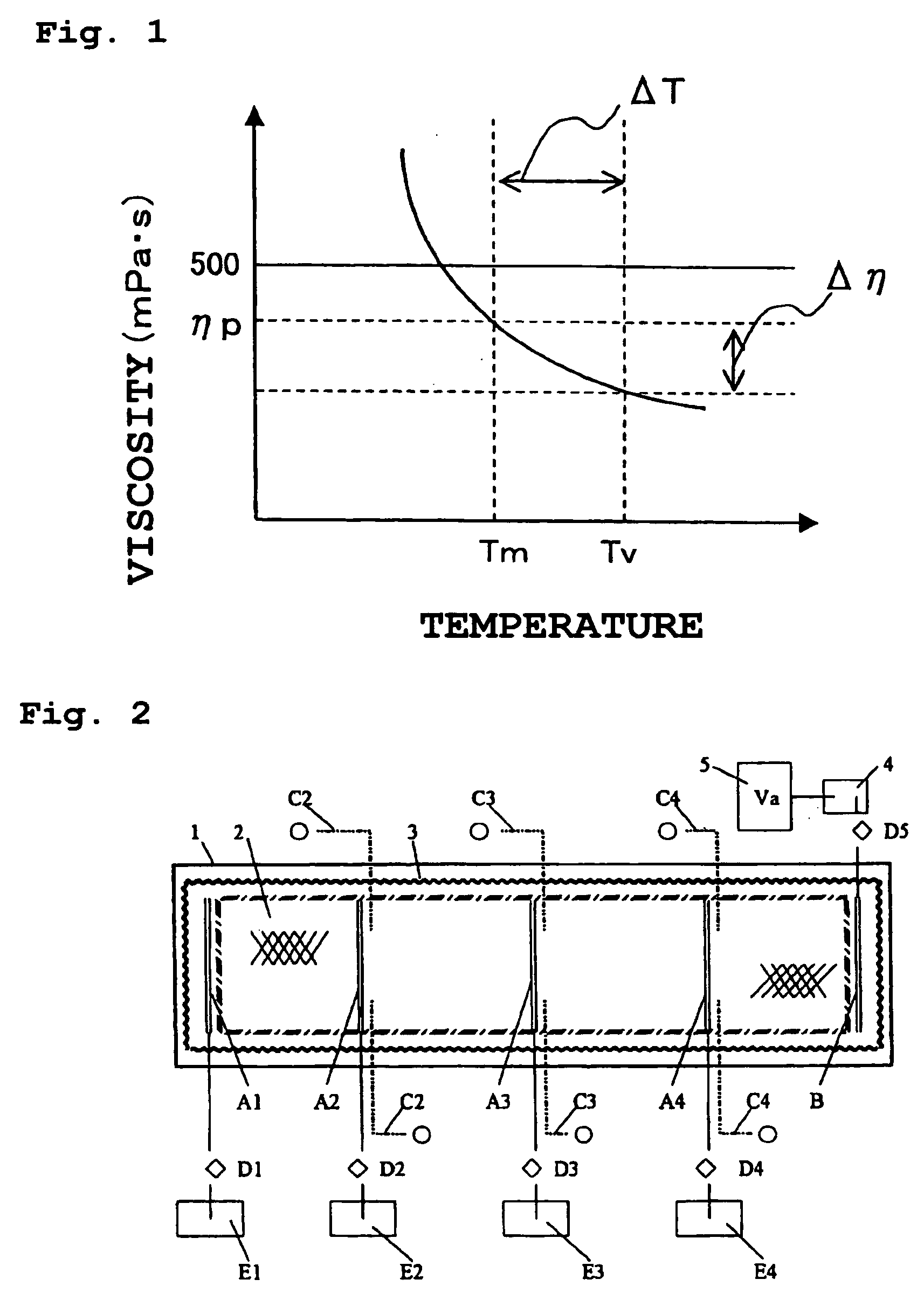
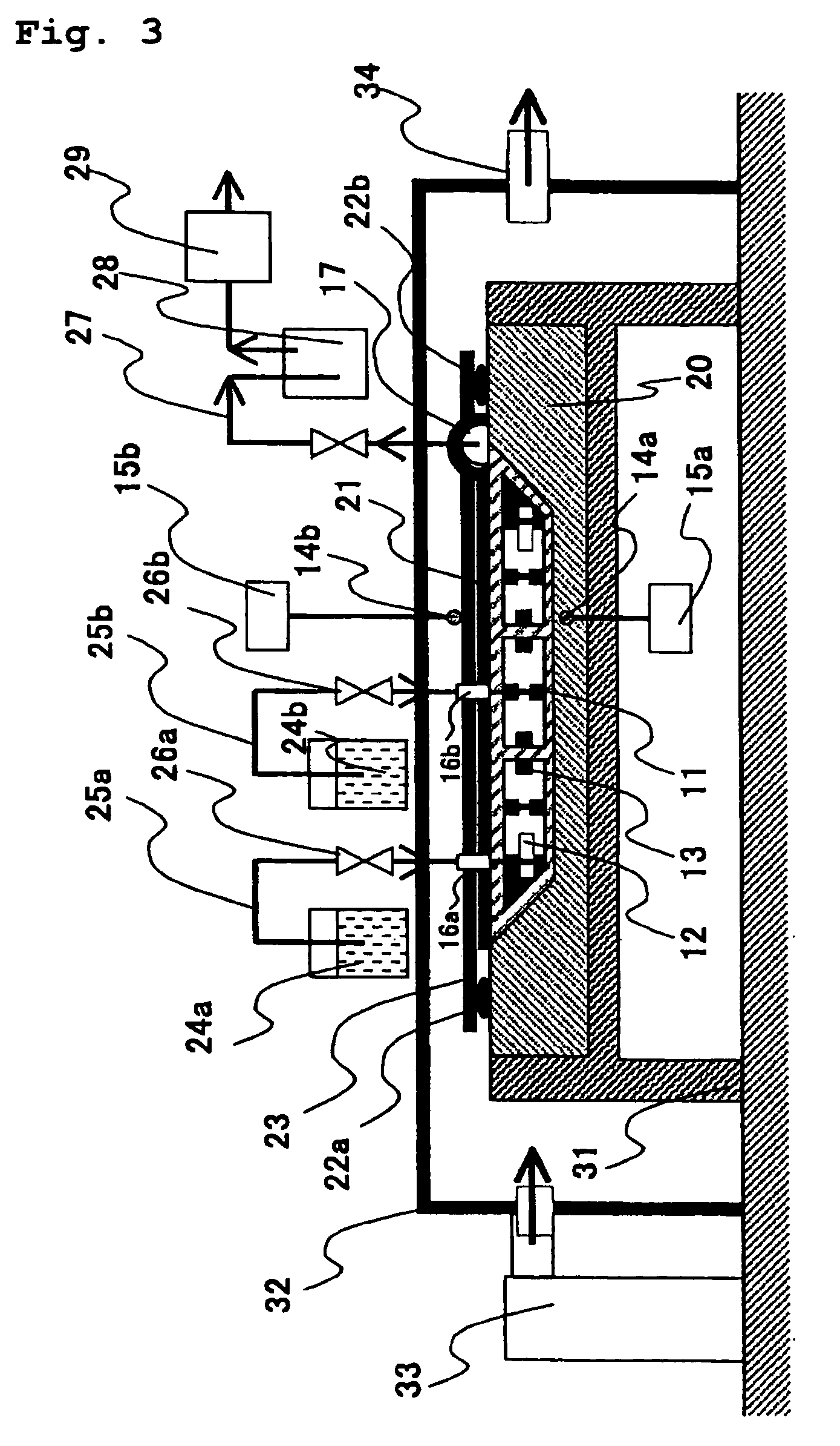
[0182] The molding die 1 shown in FIG. 2 was a FRP-made die 21 m long and 2.5 m wide. Although not shown in this figure, the entire die was placed in a simple molding chamber (a length of 25 m, a width of 3.5 m, and a height of 2 m), and the entire periphery thereof was formed of a heat insulating material and was ready to be heated by hot air generated by a hot-air generator provided outside the molding chamber. The hot air was circulated through a predetermined path. The reinforcing fiber base material used in this example was a carbon fiber plain woven fabric "Torayca" T700 (200 g / m.sup.2 in fiber a real weight) manufactured by Toray Industries, Inc., and 16 plies thereof were totally disposed. In addition, the resin was a polyamine curable epoxy resin: TR-C32, manufactured by Toray Industries, Inc., and FIG. 4 is a graph showing the change in viscosity at 70 and 80.degree. C. measured by an E type viscometer: TVE-30 model, manufactured by Toki Sangyo Co., LTD.

[0183] On the reinf...

example 3

[0196] As another example of the present invention, an example of molding using a two-sided mold 40, according to the present invention, will be described with reference to FIG. 6 (vertical cross-sectional view of a mold), in this molding the flow of the resin cannot be observed at all.

[0197] As shown in FIG. 6, a foam core 44 wounded with a reinforcing fiber base material 43 ("Torayca" T300.times.200 g / m.sup.2 in fiber areal weight, plain woven fabric, two plies, manufactured by Toray Industries, Inc.) was placed in a cavity formed in the center of the bottom mold 42 with a metal-made top mold 41. The foam core was made of a heat stable rigid polyurethane (an expansion rate of 20 times, the size having a thickness of 12 mm, a length of 2.5 m, and a width of 1.2 m) and had small groves (a width of 1.5 mm, a depth of 2.5 mm, and a pitch of 15 mm) in two major surfaces and side surfaces in the longitudinal direction as resin flow paths. In addition, in the center of the upper surface,...


PUM

PropertyMeasurementUnit
temperatureaaaaaaaaaa
temperature Tpcaaaaaaaaaa

Abstract

The present invention relates to a method for manufacturing a large FRP member and has the following structure. The method for manufacturing a large FRP member, comprising the following steps (A) to (F). They are: setting step (A) of disposing a preform containing a reinforcing fiber base material on a surface of a molding die; sealing step (B) of covering a molding portion with a bagging material or a mold and providing at least one suction port and at least one resin injection port for sealing; evacuating step (C) of evacuating the molding portion through the suction port; hot-air heating step (D) of heating the molding portion by hot air; resin injection step (E) of injecting a thermosetting resin from the resin injection port for impregnating the reinforcing fiber base material with the resin while a temperature Tm of the molding die and a temperature Tv of the bagging material or the mold are both set to room temperature or more, and a difference DeltaT in temperature between the Tm and the Tv is set to 10° C. or less; and curing step (F) of curing the resin by maintaining the molding portion at a predetermined temperature Tpc which is equal to or more than room temperature. Preferably, the preform described above includes the reinforcing fiber base material and a resin distribution medium. In addition, it is preferable that in the hot-air heating step (D), the molding die be placed in a sealed chamber which is heat insulated with a heat insulating material, the hot air be circulated and supplied, and timing of starting the injection of the resin from a plurality of the resin injection ports be controlled in accordance with signals supplied from resin detection sensors provided in the molding die. The present invention provides a method for manufacturing a large FRP member having superior quality at an inexpensive cost and with high production yield, in which non-impregnated portions and voids are unlikely to be formed.

Description

[0001] The present invention relates to methods for manufacturing fiber reinforced plastics (hereinafter referred to as "FRP") having superior qualities with high productivity. In more particular, the present invention related to a method for manufacturing a large FRP member, in which a FRP having superior qualities can be obtained at an inexpensive cost and with improved production yield, and non-impregnated portions or voids are unlikely to be formed.[0002] Due to requirements, for example, for obtaining superior dynamic characteristics or saving weight, FRP, in particular, carbon fiber reinforced plastics (hereinafter referred to as "CFRP") have been used primarily for members used in the fields of the space and aircraft industry or sport industry. For example, the FRP described above have been used for members of the space and aircraft applications, which include primary structural materials (fuselages, main wings, tail units, wing ribs, and the like) and secondary structural ma...

Claims


Application Information

Patent Timeline
Patent Type & Authority Applications(United States)
IPC IPC(8): B29C39/10B29C39/24B29C39/38B29C70/44B29C70/48B29C70/54B29K101/10B29K105/06B29K307/04
CPCB29C70/443B29C70/48B29C70/547B29K2105/0845B29L2031/3085B29L2031/3055B29L2031/3064B29L2031/3067B29L2031/3082B29K2707/04
Inventor SEKIDO, TOSHIHIDEKITANO, AKIHIKOWADAHARA, EISUKENOMA, FUMIAKI
Owner TORAY IND INC
Why Eureka
Try Eureka