Polymer electrolyte fuel cell

a fuel cell and polymer electrolyte technology, applied in the direction of electrochemical generators, cell components, coatings, etc., can solve the problems of unstable cell voltage at a high current density, insufficient reaction area, uneven contact between polymer electrolyte and catalyst, etc., to achieve the effect of increasing reaction area, reducing catalyst waste, and improving performan

Active Publication Date: 2004-07-08
PANASONIC CORP
View PDF8 Cites 54 Cited by
  • Summary
  • Abstract
  • Description
  • Claims
  • Application Information

AI Technical Summary

Benefits of technology

0066] FIG. 4 is a concept view showing the relationship between the primary particles of the carbon particles and the polymer electrolyte used by the present invention. As shown in FIG. 4, most of the carbon particles also have pores 33 in the primary particles 31. The catalyst particles 35 have a particle size of 1 to 5 nm. Therefore, the catalyst particles 35 can be sufficiently carried in the pores 33 of the primary particles 31. However, as shown in FIG. 5(a), when the particle size of a polymer electrolyte 36 is larger than the pore 33, the polymer electrolyte 36 cannot enter the pores 33 and cannot come into contact with the catalyst 35 in the pores 33, and conse

Problems solved by technology

With the above-mentioned techniques, however, since a carbon powder carrying a catalyst and a water repellent agent such as a fluorocarbon resin, or a carbon powder subjected to water repellent treatment are added simultaneously to a polymer electrolyte solution, a large amount of the polymer electrolyte adheres to the water repellent agent or the carbon powder subjected to the water repellent treatment, and accordingly the degree of contact between the polymer electrolyte and the catalyst becomes uneven, resulting in a drawback that a sufficient reaction area is not secured in the interface between the electrode and the polymer electrolyte membrane.
Besides, when the electrode is fabricated using only a carbon powder carrying a catalyst and a polymer electrolyte, there is a drawback that the cell voltage at a high current density is unstable due to flooding caused by generated water.
However, this method has a problem that, when a conventionally used perfluorocarb

Method used


Image

  • Polymer electrolyte fuel cell
  • Polymer electrolyte fuel cell
  • Polymer electrolyte fuel cell

Examples


example 2

[0074] In this example, a fuel cell was produced using Ketjen Black EC (available from AKZO Chemie, Netherlands), conductive carbon particles with an average primary particle size of 30 nm, as carbon for carrying a catalyst. Other structures and the manufacturing method are the same as in Example 1. This fuel cell is denoted as B.

[0075] Moreover, a similar fuel cell was produced using Ketjen Black 600JD (available from AKZO Chemie, Netherlands), conductive carbon particles with an average primary particle size of 30 nm, as carbon for carrying a catalyst. This fuel cell is denoted as C.

example 3

[0086] Fuel cells were produced in the same manner as in Example 1 by using Vulcan XC-72R and Black pearls 2000 manufactured by Cabot, U.S.A., Conductex 975 manufactured by Columbian Chemicals Company, U.S.A., and acetylene black product Nos. AB1, AB2, AB3 and AB18 manufactured by Denki Kagaku Kogyo K.K. as typical examples of carbon particles with pores in the agglomerate structure having a peak between 5 and 100 nm. These carbon particles are represented by letters f, g, h, I, j, k and l, respectively. When these cells were evaluated by the same method as in Example 1, they exhibited characteristics as good as the cell A.

[0087] The pore distribution of the various carbon particles used in the above-mentioned cells were measured by a mercury penetration method using AoToPore 9220 manufactured by Micromeritics. The results are shown in FIG. 8. In addition, the obtained pore size peak and the specific surface area are shown in Table 1. The carbon particles used in the cells B, C and ...

example 4

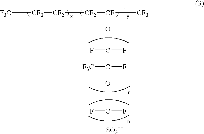
[0095] First, a carbon black powder was used as the carbon particles having a primary particle size of not smaller than 10 nm and not greater than 150 nm, and a perfluorosulfonic acid having the chemical structure represented by the following formula (3) was used as the hydrogen ion conductive polymer electrolyte. In the formula (3), m=1, n=2,

5.ltoreq.x.ltoreq.13.5, y=1000. 1

[0096] 80 parts by weight of ethanol in which 9 wt % hydrogen ion conductive polymer electrolyte was dispersed was mixed in a ball mill with 20 parts by weight of the carbon powder so as to prepare an ink for producing electrodes. Next, an ethanol in which 9 wt % hydrogen ion conductive polymer electrolyte was dispersed was casted on a smooth glass substrate, and dried to obtain a hydrogen ion conductive polymer electrolyte membrane with an average film thickness of 25 .mu.m.

[0097] Next, a 10 .mu.m thick porous carbon fabric made of carbon fibers with an average fiber diameter of 5 .mu.m was attached to both sur...


PUM


Abstract

In a polymer electrolyte fuel cell including a hydrogen ion conductive polymer electrolyte membrane; a pair of electrodes composed of catalyst layers sandwiching the hydrogen ion conductive polymer electrolyte membrane between them and gas diffusion layers in contact with the catalyst layers; a conductive separator plate having a gas flow channel for supplying a fuel gas to one of the electrodes; and a conductive separator plate having a gas flow channel for supplying an oxidant gas to the other electrode, in order to bring a hydrogen ion conductive polymer electrolyte and a catalyst metal of the catalyst layers containing the hydrogen ion conductive polymer electrolyte and conductive carbon particles carrying the catalyst metal sufficiently and uniformly into contact with each other, the polymer electrolyte is provided in pores of an agglomerate structure of the conductive carbon particles. Consequently, the reaction area inside the electrodes is increased, and higher performance is exhibited.

Description

[0001] The present invention relates to fuel cells that use pure hydrogen, reformed hydrogen obtained from methanol or fossil fuel, or liquid fuel such as methanol, ethanol and dimethyl ether directly as a fuel and use air or oxygen as an oxidant, and more particularly relates to an improvement of the catalyst layers of the electrodes of fuel cells using a polymer electrolyte.[0002] A fuel cell using a polymer electrolyte generates electric power and heat simultaneously by electrochemically reacting a fuel gas containing hydrogen with an oxidant gas containing oxygen such as air. This fuel cell is basically composed of a polymer electrolyte membrane for selectively transporting hydrogen ions; and a pair of electrodes arranged on both surfaces of the polymer electrolyte membrane. The electrode is usually composed of a catalyst layer comprising a carbon powder carrying a platinum group metal catalyst, and a hydrogen ion conductive polymer electrolyte; and a gas diffusion layer having ...

Claims


Application Information

Patent Timeline
IPC IPC(8): B05D5/12H01M4/86H01M4/88H01M4/92H01M4/96H01M8/10
CPCH01M4/8605H01M4/861H01M4/8814H01M4/8821Y02E60/50H01M4/921H01M4/926H01M8/0234H01M2008/1095H01M4/8828H01M4/86
Inventor YASUMOTO, EIICHIYOSHIDA, AKIHIKOUCHIDA, MAKOTOGYOTEN, HISAAKIHATOH, KAZUHITOSUGAWARA, YASUSHIMORITA, JUNJIKANBARA, TERUHISATAKEBE, YASUOHOSAKA, MASATONIIKURA, JUNJI
Owner PANASONIC CORP
Why Eureka
Try Eureka