Cylindrical water vapor reforming unit

a technology of cylindrical steam and reforming unit, which is applied in the direction of gas-gas reaction process, sustainable manufacturing/processing, separation process, etc., can solve the problems of unit delay in temperature rise, complex structure, and low internal thermal performan

Inactive Publication Date: 2004-07-29
TOKYO GAS CO LTD
View PDF5 Cites 47 Cited by
  • Summary
  • Abstract
  • Description
  • Claims
  • Application Information

AI Technical Summary

Problems solved by technology

(1) This reforming unit needs a heat insulation layer (79), a cooling mechanism (80) and the like in the inside thereof and thus, not only the structure becomes complicated, but also the internal thermal performance is low owing to the fact that because the heat insulation layer (79) and the cooling mechanism (80) are, respectively, interposed between these catalyst layers, the respective catalyst layers are separated from one another and are not contiguous, thereby causing the unit to be delayed in temperature rise upon startup and having the startup time prolonged in practice.
(3) Because the usable temperature of the CO shift catalyst layer (75) is limited to 200.about.300.degree. C., the reaction velocity caused by the catalyst is so low that a large amount of the CO shift catalyst is required, which renders the unit large in size, thereby increasing the weight correspondingly.

Method used


Image

  • Cylindrical water vapor reforming unit
  • Cylindrical water vapor reforming unit
  • Cylindrical water vapor reforming unit

Examples


example

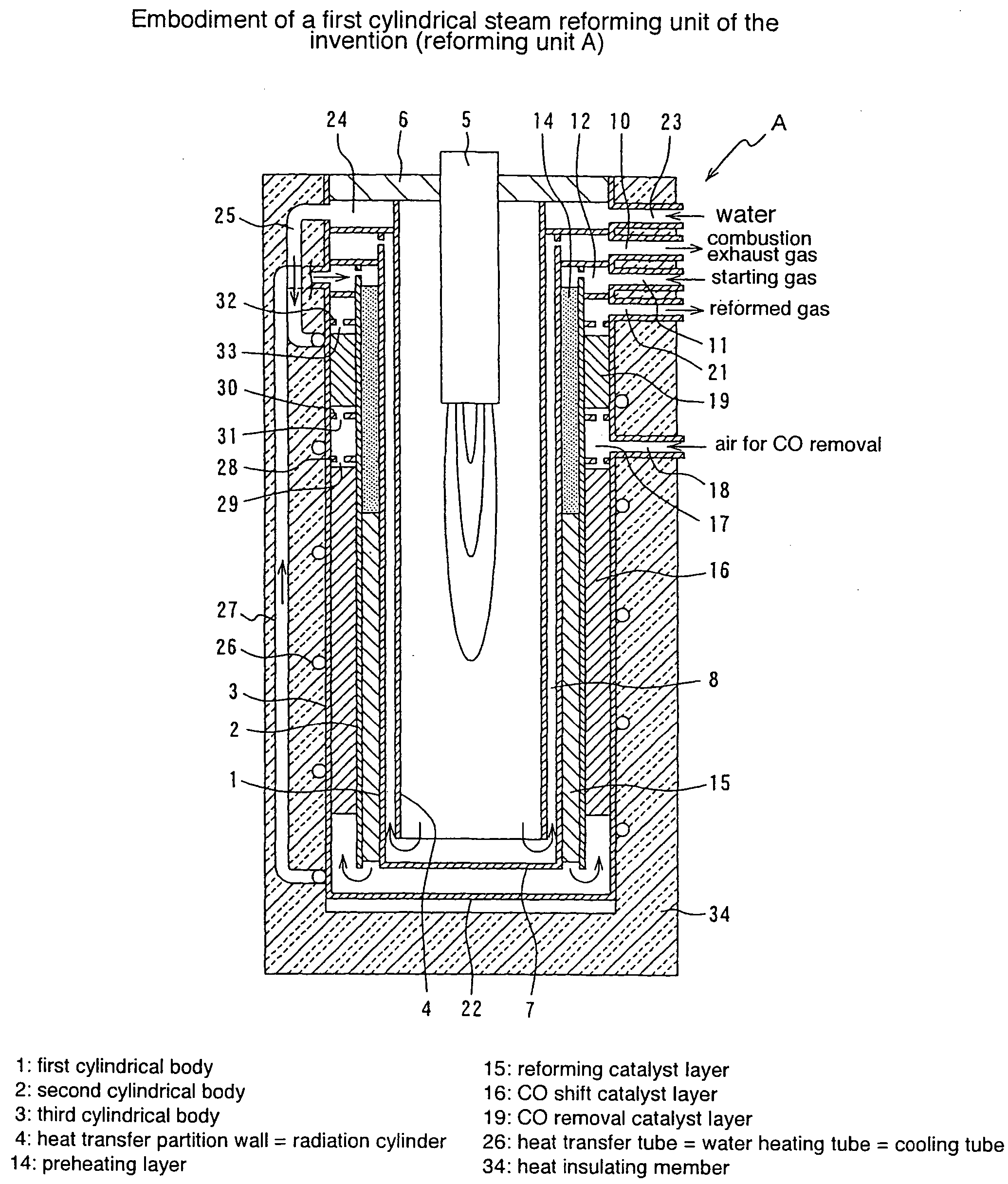
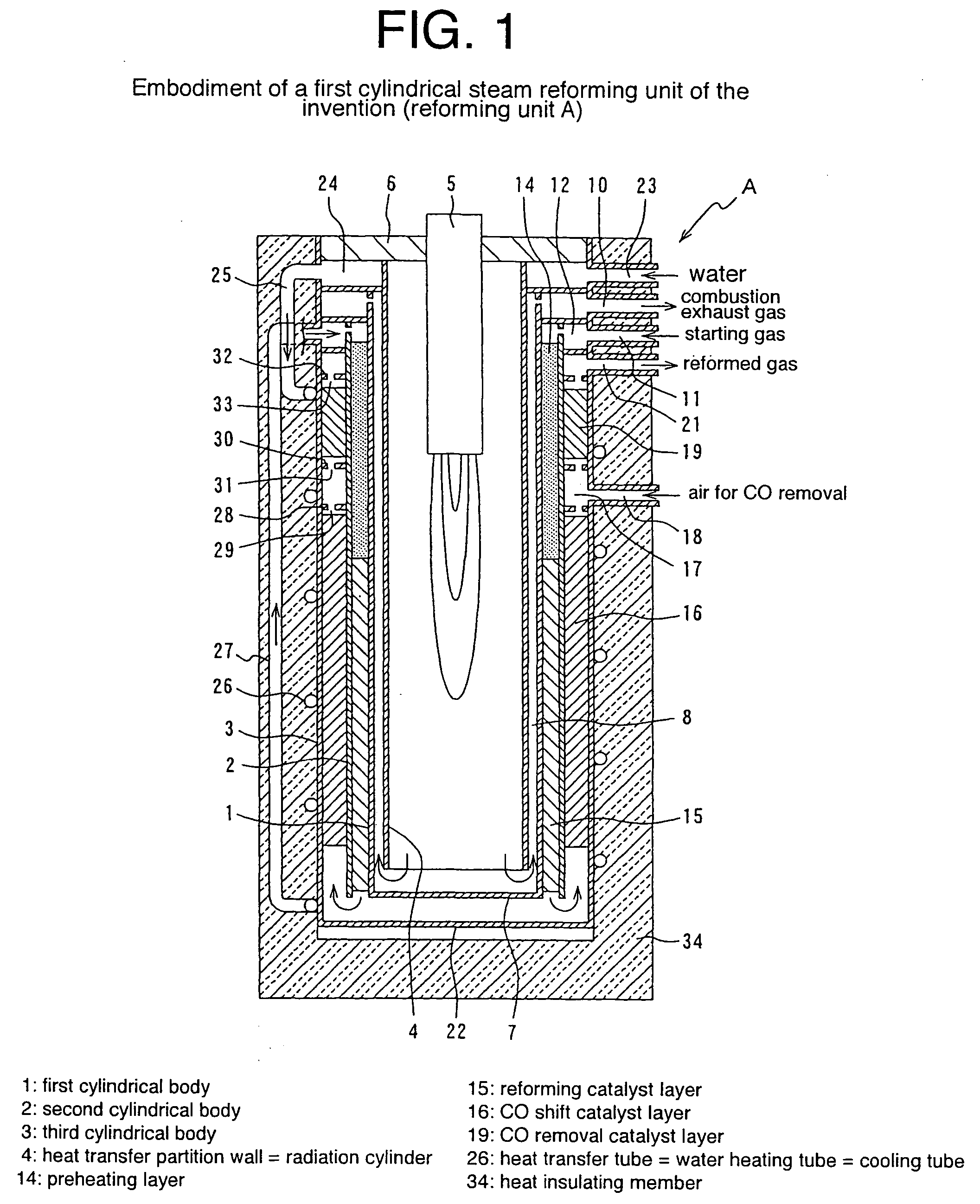
[0071] The invention is described in detail byway of example, which should not be construed as limiting the invention thereto. This examples was carried out by use of the reforming unit A shown in FIG. 1. PEFC (polymer electrolyte fuel cell with output power=1 to 1.2 kW) was connected to the reforming unit A wherein a reformed gas prepared in the reforming unit A was used as a fuel of PEFC.

[0072] The respective types of catalysts were packed in the reforming catalyst layer, CO shift catalyst layer and CO removal catalyst layer, and temperature sensors were, respectively, disposed in these layers as usual. For a reforming catalyst, a ruthenium catalyst (i.e. a catalyst supporting Ru on granular alumina) was used. The CO shift catalyst used included a platinum catalyst (i.e. a catalyst supporting Pt on granular alumina) at a high temperature portion of the CO shift catalyst layer and a Cu / Zn catalyst (i.e. a catalyst supporting Cu and Zn on granular alumina) at a lower temperature por...


PUM

PropertyMeasurementUnit
temperatureaaaaaaaaaa

Abstract

A cylindrical steam reforming unit comprising a plurality of cylindrical bodies consisting of a first cylindrical body, a second cylindrical body and a third cylindrical body of successively increasing diameters disposed in a concentric spaced relation, a radiation cylinder disposed within and concentrically with the first cylindrical body, a burner disposed in the radial central portion of the radiation cylinder, and a reforming catalyst layer with a reforming catalyst filled in a gap between the first and second cylindrical bodies, wherein a CO shift catalyst layer and a CO removal catalyst layer are disposed in a gap between the second and third cylindrical bodies, the CO shift catalyst layer being formed in a gap with the direction of flow reversed at one axial end of the reforming catalyst layer and through a heat recovery layer of predetermined length. According to this reforming unit, without internally disposing a heat insulation layer, a cooling mechanism or the like, the reforming catalyst layer, CO shift catalyst layer, and CO removal catalyst layer can be integrated, achieving various useful effects, including size and weight reductions and the shortening of startup time.

Description

TECHNICAL FILED[0001] This invention relates to a cylindrical steam reforming unit for preparing an reformed gas mainly composed of hydrogen by subjecting, to steam reforming, hydrocarbon fuels such as city gas, LPG and the like and more particularly, to a cylindrical steam reforming unit used in Polymer Electrolyte Fuel Cell (PEFC).TECHNICAL BACKGROUND[0002] For reforming units of steam reforming a starting gas such as a city gas, LPG, a natural gas or the like, a reforming unit described, for example, in WO 00 / 63114 is known. This reforming unit is one that is to prepare a reformed gas of high hydrogen concentration mainly used in a polymer electrolyte fuel cell and as shown in FIG. 5, a burner (70) is disposed at the center of a plurality of cylindrical tubular bodies (61.about.69) wherein a combustion gas passage (71), a preheating layer (72), a reforming catalyst layer (73), a heat recovery layer (74), a CO shift catalyst layer (75), a CO removal catalyst layer (78) and the lik...

Claims


Application Information

Patent Timeline
Patent Type & Authority Applications(United States)
IPC IPC(8): B01J8/04C01B3/38C01B3/48
CPCB01J8/0465C01B2203/82B01J8/0496B01J2208/00203B01J2208/00495B01J2208/00504B01J2208/0053C01B3/384C01B3/48C01B2203/0233C01B2203/0283C01B2203/044C01B2203/047C01B2203/066C01B2203/0811C01B2203/0816C01B2203/0822C01B2203/0827C01B2203/0844C01B2203/0866C01B2203/0894C01B2203/1011C01B2203/1023C01B2203/80B01J8/0492Y02P20/10
Inventor MIURA, TOSHIYASU F.KOMIYA, JUNFUJIKI, HIROSHIFUJIWARA, NAOHIKO
Owner TOKYO GAS CO LTD
Why Eureka
Try Eureka