Thermally integrated fuel cell power system

a fuel cell and power system technology, applied in the direction of fuel cells, fuel cell heat exchange, electrochemical generators, etc., can solve the problems of insufficient heat recovery, complex and costly fuel cell systems, and insufficient heat recovery

Inactive Publication Date: 2004-07-29
GAS TECH INST
View PDF9 Cites 56 Cited by
  • Summary
  • Abstract
  • Description
  • Claims
  • Application Information

AI Technical Summary

Problems solved by technology

Due to the limited electricity generating capacity of individual fuel cell units, a plurality of fuel cell units are typically stacked one on top of another with a bipolar separator plate separating the fuel cell units between the anode electrode of one fuel cell unit and the cathode electrode of an adjacent fuel cell unit.
However, a significant issue in the operation of high temperature fuel cells is heat management, in particular minimizing the amount of heat loss.
Conventional fuel cell power systems for operation of high temperature fuel cell stacks are limited in thermal integration for heat recovery because of the use of discrete heat exchangers, which require extensive ducting and thermal insulation.
This approach has made these fuel cell systems both complex and costly to manufacture and tends to place constraints on fuel cell stack design configurations to support the required plumbing system.
However, the disclosed design only provides for single stage heating of the oxidant inlet by a single heat exchange which would not raise the ambient air for the oxidant to the required operating temperature range of the solid oxide fuel cell stack due to the very limited surface and residence time to which the gas would be subjected.
In addition, other key requirements such as fuel feedstock preheating prior to reformation, heating needs during system start-up from ambient conditions and partial load operations are also not addressed by this disclosure.
However, the disclosed structure does not provide any means for heat recovery, which is critical for efficient operation and cost effective system operation.
Although addressing the need for heat recovery and transfer to the fuel feedstock as well as support for the reformation reaction, the heating of the air for the oxidant feedstock is not integrated and is provided by external means resulting in system inefficiency and fabrication complexity.
However, the highest temperature effluent stream is not fully utilized in this configuration for heat recovery because of its containment inside of the fuel cell stack in the oxidant outlet internal manifold.

Method used


Image

  • Thermally integrated fuel cell power system
  • Thermally integrated fuel cell power system
  • Thermally integrated fuel cell power system

Examples


Embodiment Construction

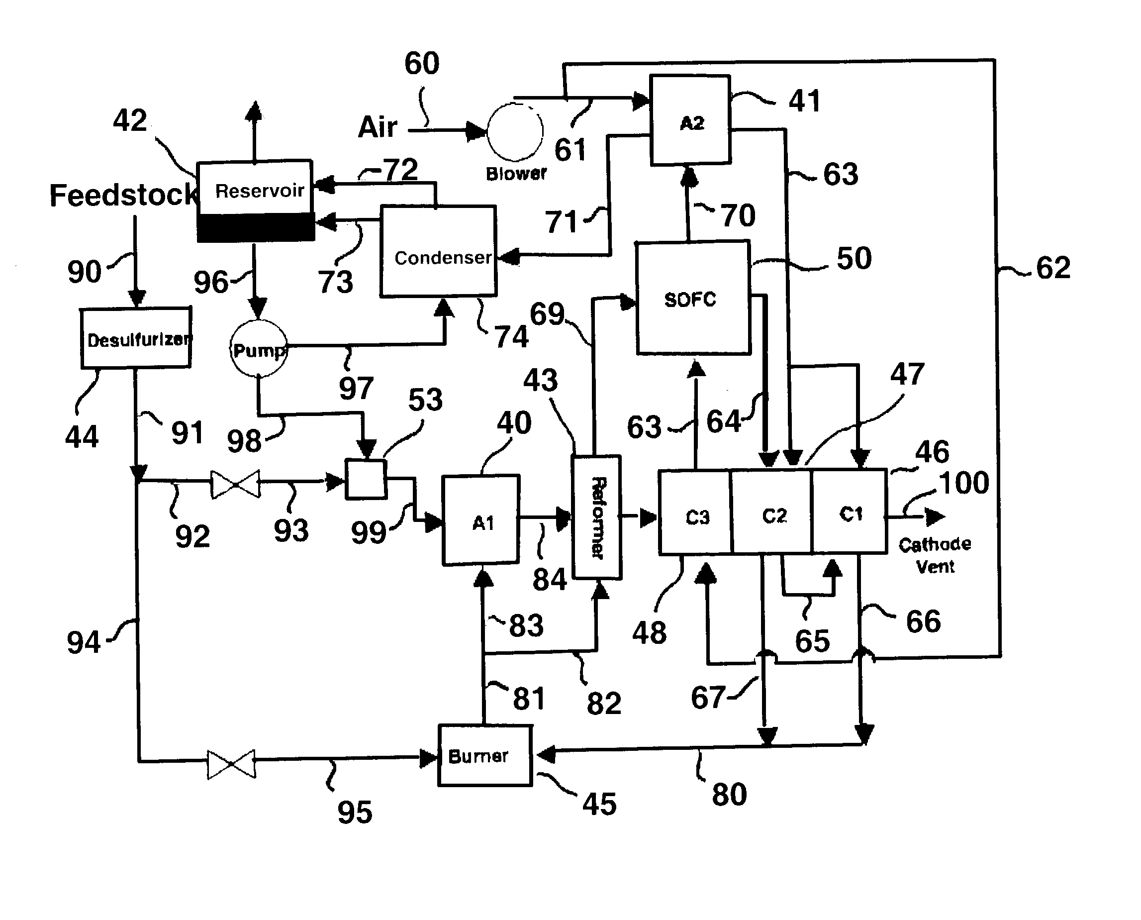
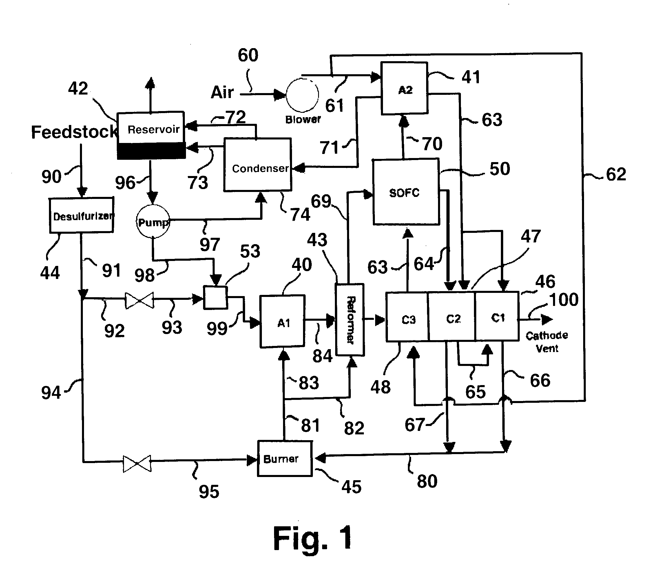
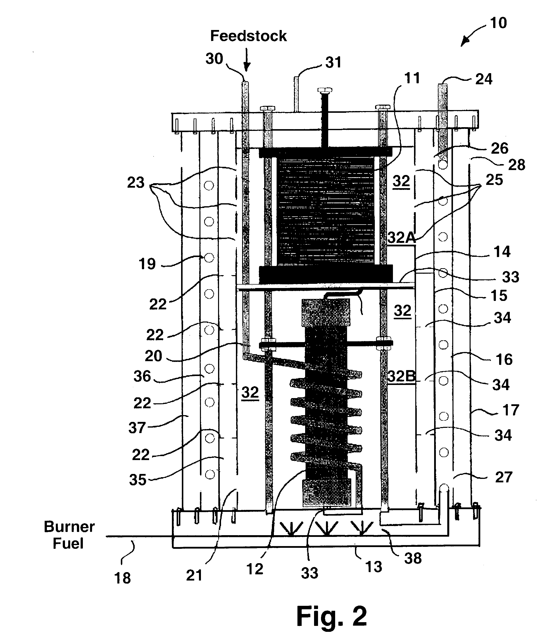
[0021] As previously stated, the basic approach of this invention is the thermal integration of system components in which the highest temperature components are located and enclosed within the core of the assembly. Concentric, or layered, walls can then be employed to accomplish any system heat management goal. For example, in accordance with one embodiment, the highest temperature of the fuel cell power system of this invention is maintained within the core and each subsequent annulus, ordered from the inside, or assembly core, to the outside is engineered to operate at a decreased temperature. In accordance with another embodiment, the highest temperature of the fuel cell power system is maintained in the core, but with the first annulus out from the core containing the coolest stream, for instance, ambient inlet air, to maximize heat removal from the fuel cell stack by means of a tailored combination of conduction, convection and radiation. Embodiments may also be employed to su...


PUM

PropertyMeasurementUnit
operating temperatureaaaaaaaaaa
heataaaaaaaaaa
chemical energyaaaaaaaaaa

Abstract

A fuel cell power system having at least one fuel cell stack, at least one fuel processor in fluid communication with the at least one fuel cell stack and heat exchangers for transferring heat between the at least one fuel cell stack and the at least one fuel processor in which the at least one fuel cell stack and the at least one fuel processor are circumferentially surrounded by a plurality concentric heat exchanger shell assemblies.

Description

[0001] 1. Field of the Invention[0002] This invention relates to a fuel cell power system comprising a fuel cell stack, fuel processor and heat exchangers. More particularly, this invention relates to a fuel cell power system in which the fuel cell stack, fuel processor and heat exchange components are disposed in one thermally integrated assembly. The fuel cell power system of this invention is particularly suitable for use with solid oxide fuel cells and solid oxide fuel cell stacks.[0003] 2. Description of Related Art[0004] A fuel cell is an electrochemical device in which the chemical energy of a reaction between a fuel and an oxidant is converted directly into electricity. The basic fuel cell unit comprises an electrolyte layer in contact with a porous anode and cathode on either side. In a typical fuel cell, a gaseous or liquid fuel is continuously fed to the anode electrode, sometimes referred to as the fuel electrode, and an oxidant, such as oxygen from air, is continuously ...

Claims


Application Information

Patent Timeline
Patent Type & Authority Applications(United States)
IPC IPC(8): H01M8/04H01M8/06H01M8/12H01M8/24
CPCH01M8/04007H01M8/04022Y02E60/50H01M8/247H01M8/0612
Inventor PONDO, JOSEPH M.GOODWIN, DAVID J.SISHTLA, CHAKRAVARTHYPETRI, RANDY J.REMICK, ROBERT J.
Owner GAS TECH INST
Why Eureka
Try Eureka