

Method for recycling composite materials
- Summary
- Abstract
- Description
- Claims
- Application Information
AI Technical Summary
Benefits of technology
Problems solved by technology
Method used
Image

Examples
example of embodiment
OF THE INVENTION
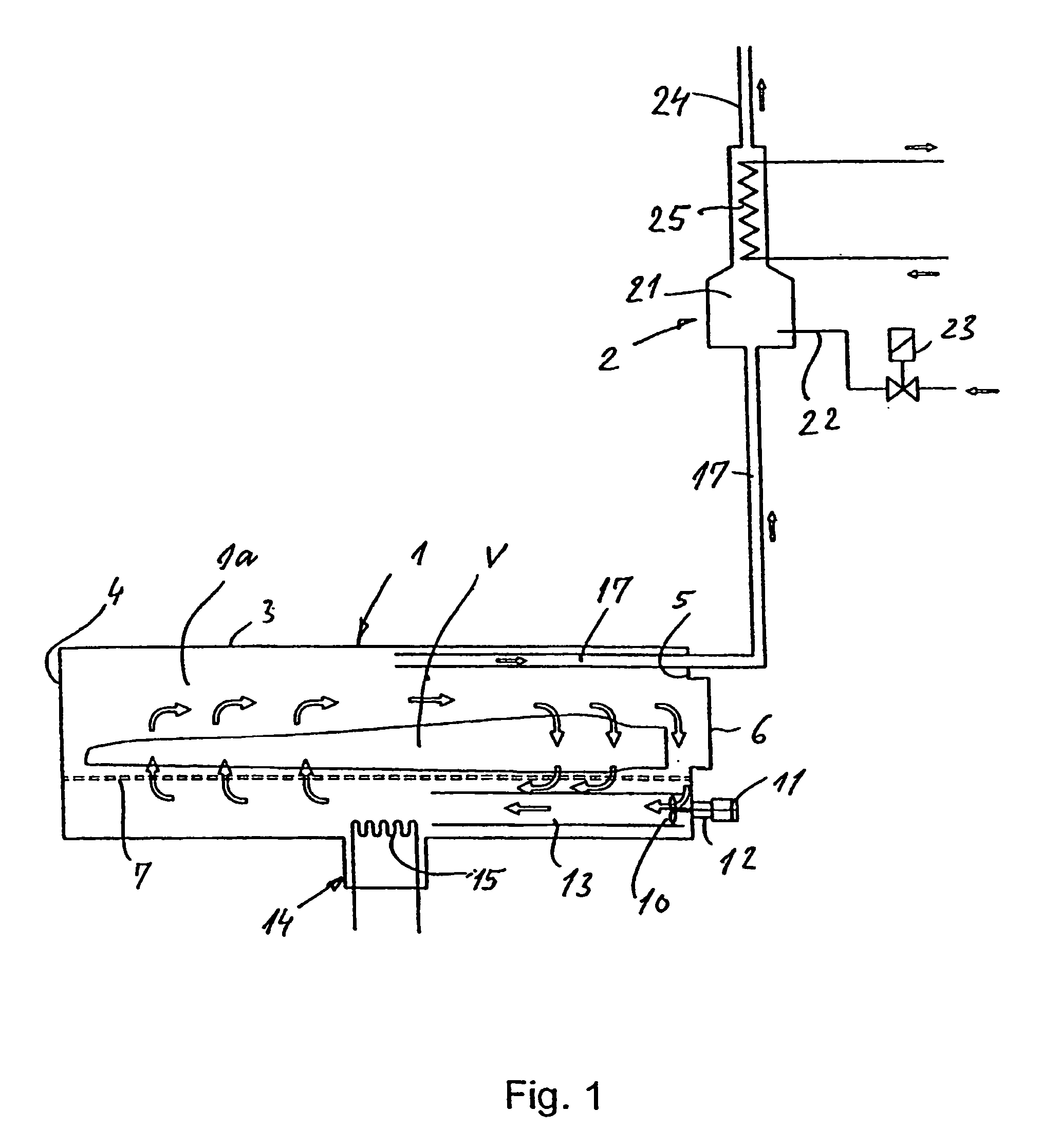
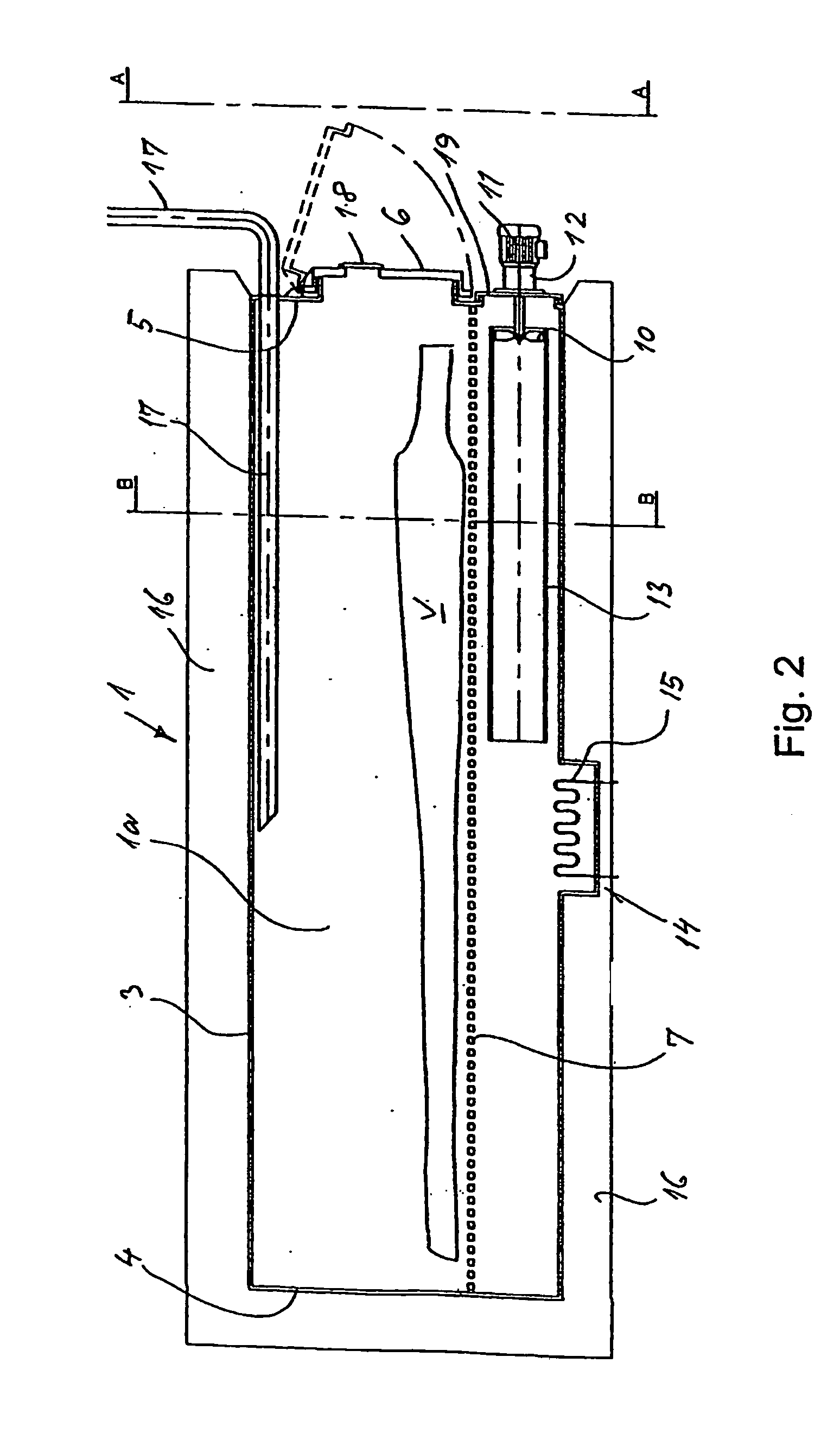
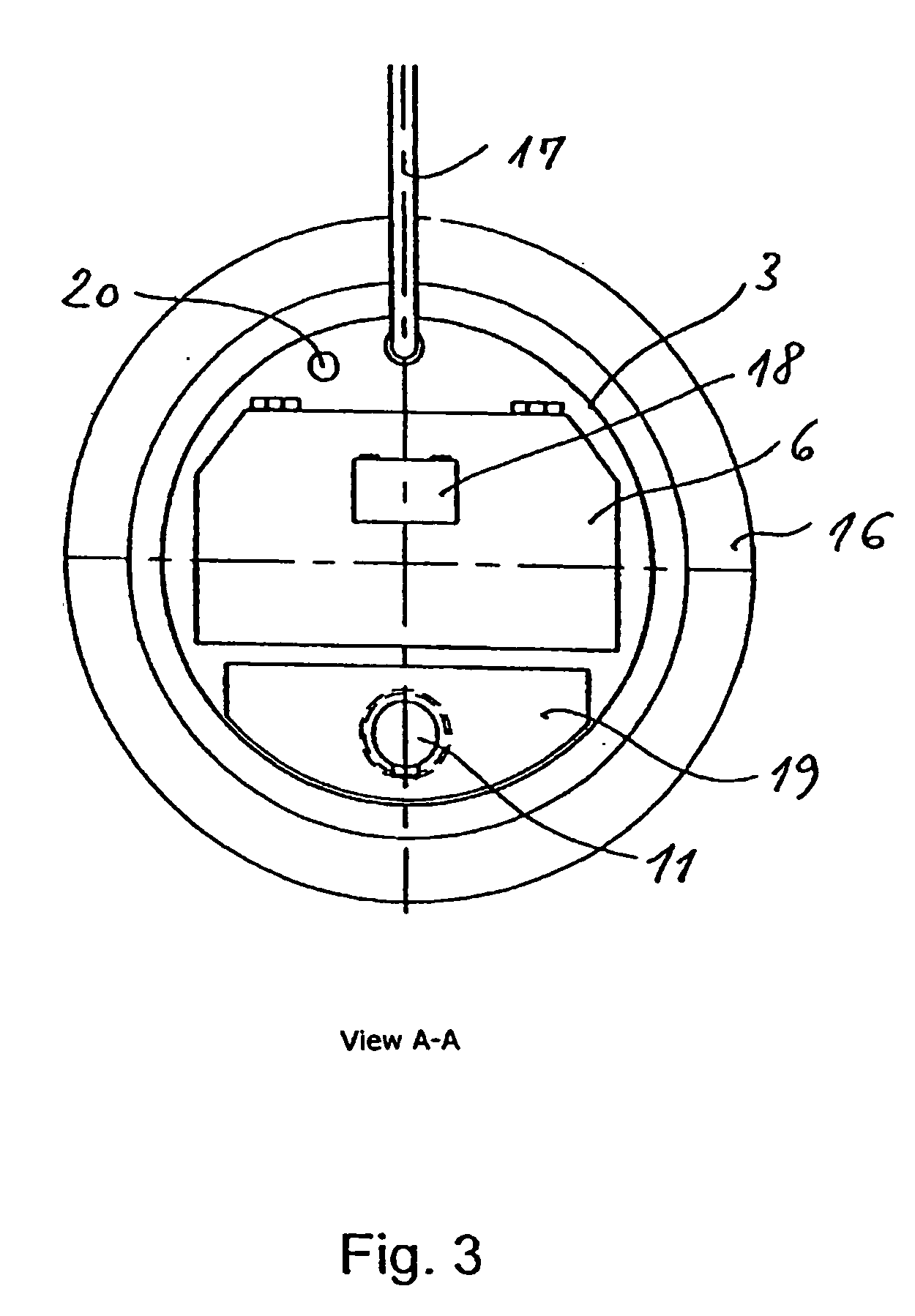
[0017] According to the invention, the described separation process may, in combination with utilisatlon of the energy of the resulting gas, advantageously be carried out in a plant consisting mainly of a closed pyrolysis furnace and a combustion chamber for the gases generated in the pyrolysis process. The size of the pyrolysis furnace is adapted to the largest items to be destructed, so that breaking of the material is avoided. The furnace is suitably designed with a grid tray and with a circulation blower inserted in the furnace chamber itself so that the heated gas in the furnace may circulate effectively around all parts of the destruction item or items. Thereby, the pyrolysis process is accelerated. Heating of the furnace is effected by supplying external heat energy in the form of electricity or gas. In a particular embodiment of the invention the combustion chamber is placed inside the pyrolysis furnace. In this way it is achieved that the combustion chamber ...
PUM
| Property | Measurement | Unit |
|---|---|---|
| Temperature | aaaaa | aaaaa |
| Angle | aaaaa | aaaaa |
| Angle | aaaaa | aaaaa |
Abstract
Description
Claims
Application Information