Raman imaging and sensing apparatus employing nanoantennas

a sensing apparatus and nanoantenna technology, applied in the direction of optical radiation measurement, instruments, spectrometry/spectrophotometry/monochromators, etc., can solve the parasitic raman signal resulting from the fiber itself, fiber based delivery or collection system, etc., to facilitate nanoscale vibration spectra and high sensitivity

Inactive Publication Date: 2004-09-09
PURDUE RES FOUND INC
View PDF15 Cites 39 Cited by
  • Summary
  • Abstract
  • Description
  • Claims
  • Application Information

AI Technical Summary

Benefits of technology

0005] The present invention enables one to combine the advantages of high sensitivity of surface-enhanced Raman scattering (SERS) with sub-wavelength spatial resolution of near-field scanning optical microscope (NSOM) and nanometer resolution of atomic force microscope (AFM). The invention also facilitates nanoscale measurements of vibration spectra of molecules and their Raman and topographical imaging. The metal tip-substrate nanoantenna (MTSN) described herein makes

Problems solved by technology

Another serious drawback of a fiber based delivery or collection systems are parasitic Raman signal resulting from the fiber itself.
However, the enhancement factor is several orders of magnitude less than the enhancement for SERS in

Method used


Image

  • Raman imaging and sensing apparatus employing nanoantennas
  • Raman imaging and sensing apparatus employing nanoantennas
  • Raman imaging and sensing apparatus employing nanoantennas

Examples


Embodiment Construction

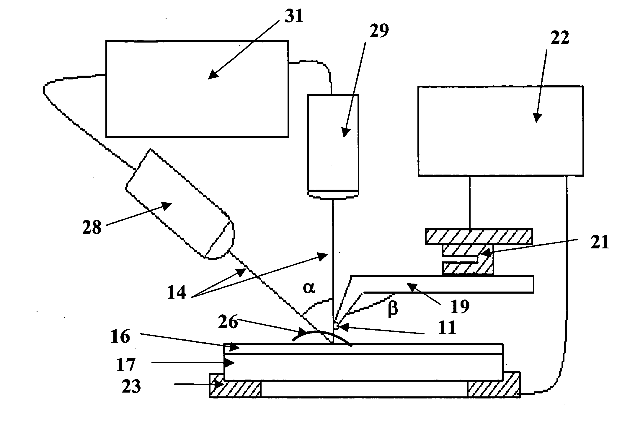
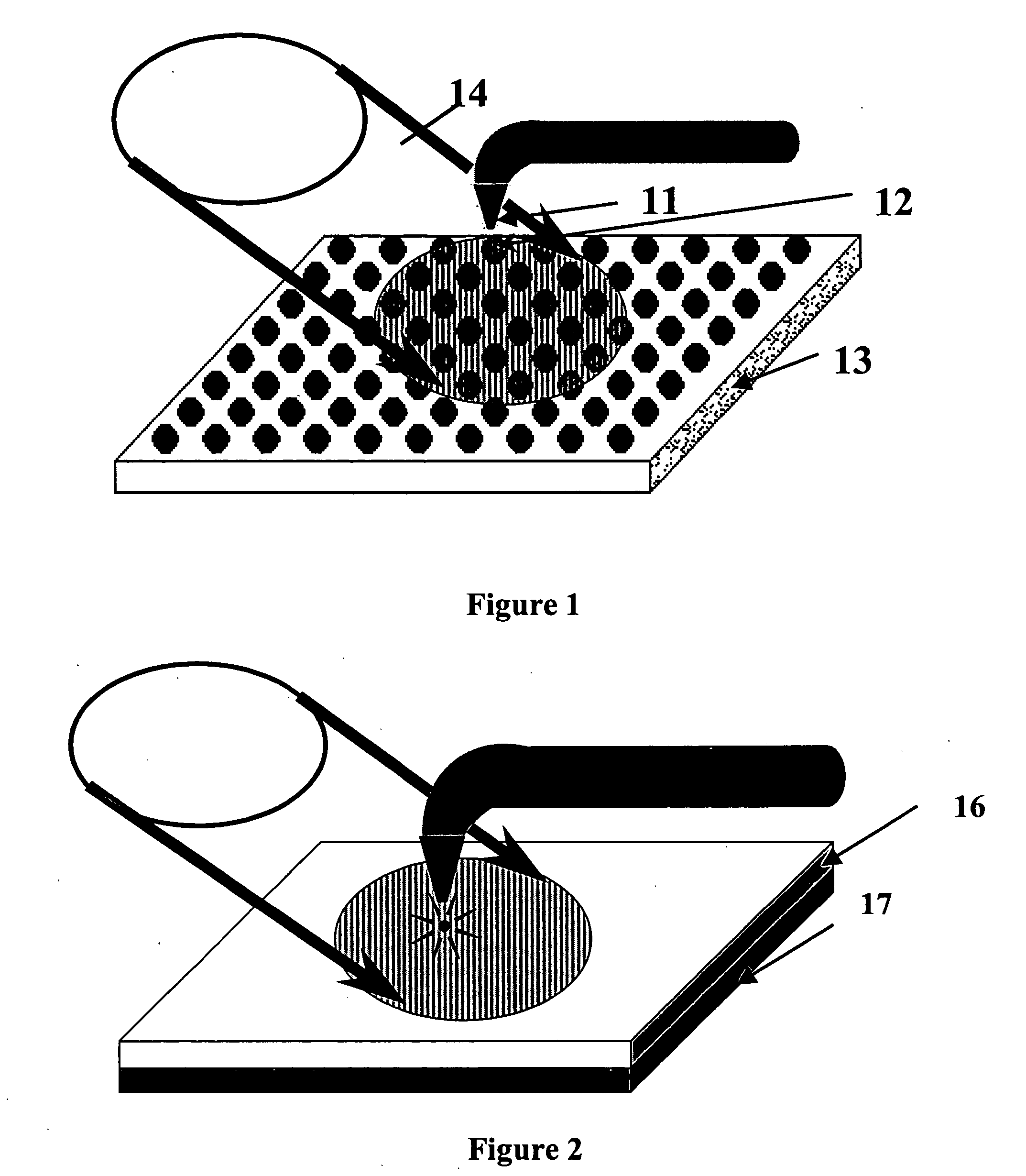
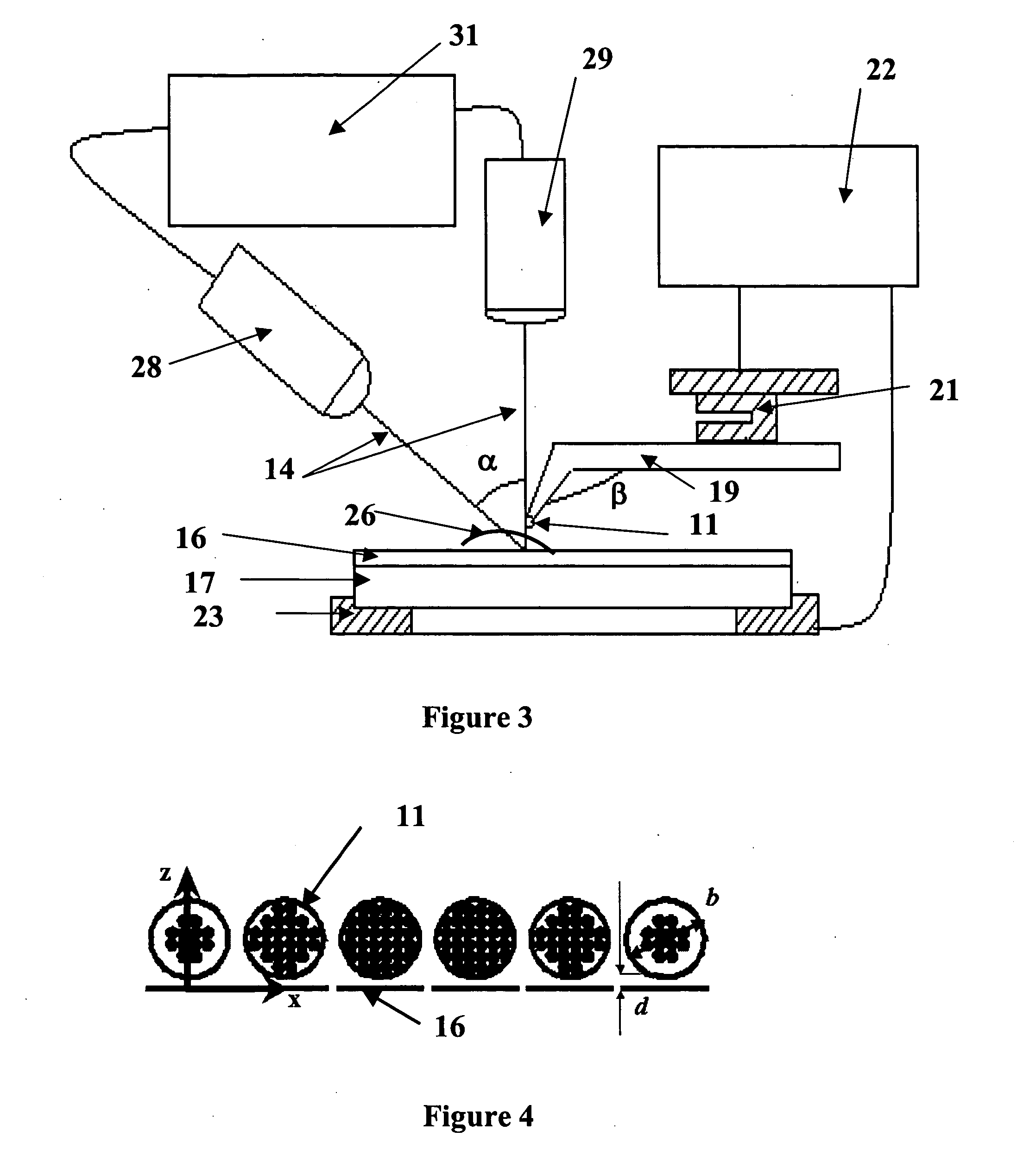
[0021] In accordance with the present invention plasmon resonance is induced by light striking a nanoantenna which comprises a metal tip and a metal substrate or particle spaced from the tip with the plasmon resonance exciting a sample at the interface to cause molecular vibrations which provide Raman scattering.

[0022] Let us estimate the advantage of using a nanoantenna instead of a single particle or tip as in the prior art SERS. One can consider the simplest nanoantenna as a pair of metal particles for this purpose. The electric field of a resonant light wave acting inside the pair is stronger than the local field in a single particle. The enhancement factors E.sub.i / E.sub.0 for a local field E.sub.i, in comparison with an incident field E.sub.0, is G=.epsilon..sub.1.sup.2 / 3.epsilon..sub.2 for a plasmon resonance in a pair [S. G. Rautian et al., JETP Lett. 47 (1988) 243] and f.sub.1=3.epsilon..sub.0 / i.epsilon..sub.2 for a single particle. Here .epsilon.=.epsilon..sub.1+i.epsilon....


PUM


Abstract

A Raman imaging and sensing apparatus is described. The apparatus employs a nanoantenna structure which includes a metal tip spaced from a metal surface or particle. A light beam impinges upon the nanoantenna and causes plasmon resonance. The plasmon resonance excites a sample resulting in dramatically enhanced Raman scattering of the sample. The Raman scatter is collected by a spectrophotometer which provides an output signal indicative of the composition of the sample.

Description

[0001] This application claims priority to U.S. Provisional Application Serial No. 60 / 453,107 filed Mar. 7, 2003.[0002] The present invention relates generally to a Raman imaging and sensing apparatus and more particularly to such apparatus which employs metal tip-substrate nanoantennas for Raman imaging and sensing of atoms, molecules, ions, etc.[0003] Raman spectroscopy measures molecular vibrations, which are determined by the structure and chemical bonding as well as the masses of constituent atoms, molecules, ions, etc. Raman spectra provide us with unique chemical and structural identification. Conventional micro-Raman spectroscopy has a spatial resolution of about 0.5 .mu.m governed by the diffraction limit and even worse for IR spectrometers because of the longer wavelengths. The near-field scanning Raman microscopy (NSRM) exploits an optical fiber tip with a small aperture to deliver laser radiation or collect the scattered light [S. Webster et al., Vibrat. Spectrosc. 18 (1...

Claims


Application Information

Patent Timeline
IPC IPC(8): G01Q30/02G01N21/65G01Q60/18G01Q70/08
CPCB82Y15/00B82Y20/00G01Q60/22G01N21/658G01N2021/656B82Y35/00
Inventor DRACHEV, VLADIMIR P.SHALAEV, VLADIMIR M.SARYCHEV, ANDREY K.
Owner PURDUE RES FOUND INC
Why Eureka
Try Eureka