Terahertz light apparatus

a light apparatus and terahertz technology, applied in the field of terahertz light technology, can solve the problems of wasting terahertz light, wasting terahertz light, and wasting terahertz light, and achieve the effect of only achieving lock-in detection

Inactive Publication Date: 2004-10-07
TOCHIGI NIKON CORP +1
View PDF8 Cites 26 Cited by
  • Summary
  • Abstract
  • Description
  • Claims
  • Application Information

AI Technical Summary

Benefits of technology

[0013] The present invention also provides a terahertz light detection method, an imaging method, an imaging device and a terahertz light device, which make it possible to improve the SN ratio by driving a terahertz light generation element through the modulation drive method.
[0020] The imaging device achieved in a seventh mode of the present invention comprises the terahertz light generation element described earlier, the terahertz light detection unit used in the fourth mode, the bias voltage control unit described above and an image acquisition means for obtaining an image signal. The image acquisition means obtains the image signal based upon a first electrical signal provided by the terahertz light detection unit while the bias voltage with a given polarity is applied between the pair of electrically conductive portions and a second electrical signal provided by the terahertz light detection unit while the bias voltage with another polarity is applied between the pair of electrically conductive portions. Namely, it obtains an image of a measurement object based upon image signals corresponding to individual positions that are output from the terahertz light detection unit. The image acquisition means may obtain each image signal by calculating the difference between the first electrical signal and the second electrical signal.

Problems solved by technology

While a CCD camera or a photoconductive antenna array is used as a detector in such a process, a lock-in amplifier must be provided for each pixel if the two-dimensional image is to be obtained through a lock-in detection, giving rise to cost and space related problems.
However, since the light chopper or the like turns on / off the terahertz light, the terahertz light is not utilized efficiently while it is in an OFF state (utilization efficiency; 50%).
Thus, a lock-in detection can only be achieved in the related art by turning on / off the terahertz light.
For this reason, as long as the lock-in detection is executed by utilizing a photonic switch element such as a photoconductive antenna as a terahertz light source, the utilization efficiency of the terahertz light cannot be improved and ultimately, the SN ratio cannot be greatly improved in the related art.
In other words, although the device is capable of generating terahertz light during this period of time, the device capability is not effectively utilized.

Method used


Image

  • Terahertz light apparatus
  • Terahertz light apparatus
  • Terahertz light apparatus

Examples


first embodiment

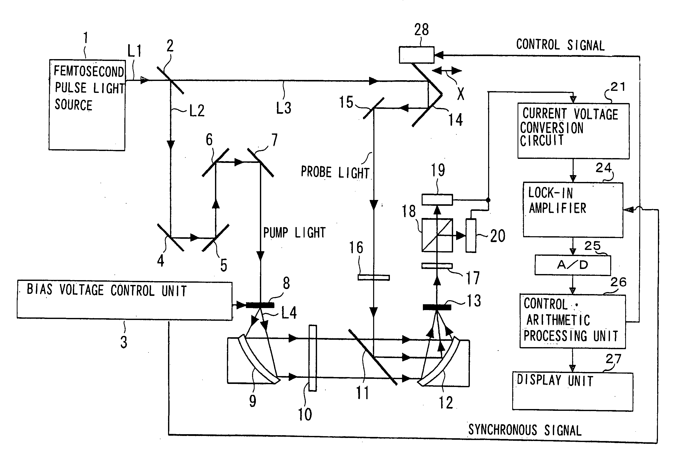
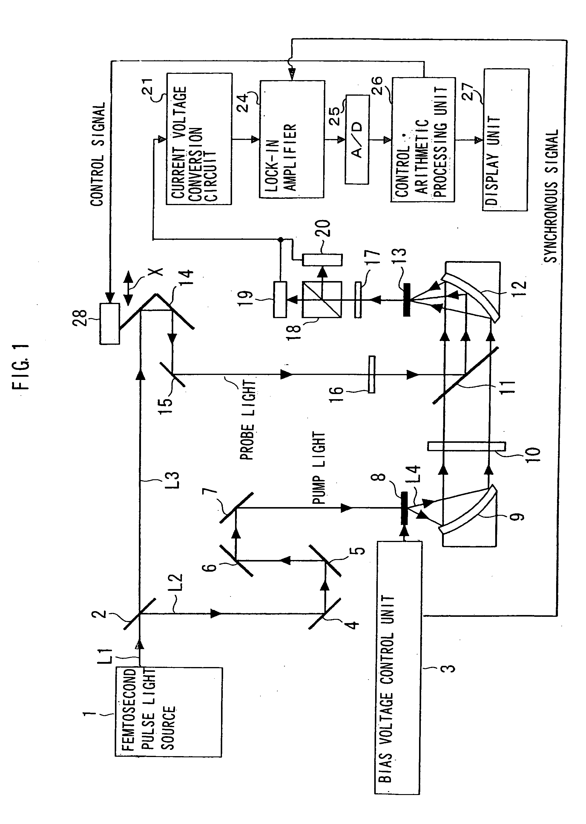
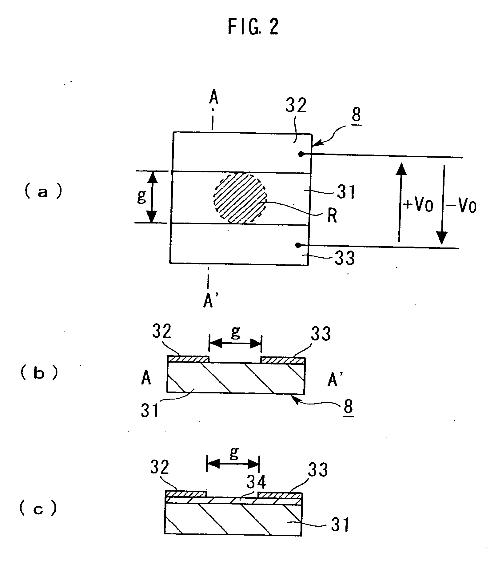
[0037] FIG. 1 schematically illustrates the structure of the terahertz light device achieved in the present invention. FIG. 2 shows examples of the terahertz light generation element 8 included in FIG. 1, with FIG. 2(a) presenting a schematic plan view of the terahertz light generation element 8, FIG. 2(b) presenting a schematic sectional view taken along line I-I in FIG. 2(a) and FIG. 2(c) presenting a schematic sectional view of a variation of the terahertz light generation element 8 shown in FIGS. 2(a) and 2(b). FIG. 2(c) corresponds to FIG. 2(b).

[0038] In the terahertz light device in this embodiment, a femtosecond pulse light beam L1 emitted from a femtosecond pulse light source 1 is split into two pulse light beams L2 and L3 at a beam splitter 2. The femtosecond pulse light source 1 in the embodiment is constituted of a laser light source or the like. The femtosecond pulse light source 1 emits linearly polarized femtosecond pulse light L1 with a central wavelength of approxima...

second embodiment

[0070] FIG. 4 schematically illustrates the structure of the terahertz light device achieved in the second embodiment of the invention. In FIG. 4, the same reference numerals are assigned to elements identical to or corresponding to elements shown in FIG. 1 to preclude the necessity for a repeated explanation thereof.

[0071] The terahertz light device in the second embodiment is an imaging device that forms an image of a measurement object 10.

[0072] In the terahertz light device in the embodiment, a femtosecond pulse light beam L1 emitted from a femtosecond pulse light source 1 passes through a plane reflecting mirror 41 and is split into pump light L2 and probe light L3 at a beam splitter 42. The pump light L2 travels through a movable mirror 43 constituted by combining two or three plane reflecting mirrors and plane mirrors 44-46, is expanded at a beam expander 47 and is then guided to a terahertz light generation element 8 adopting the structure similar to that in the first embodi...


PUM

PropertyMeasurementUnit
bias voltageaaaaaaaaaa
central wavelengthaaaaaaaaaa
lengthaaaaaaaaaa

Abstract

A terahertz light generation element 8 emits terahertz light as excitation pulse light is emitted onto an area between electrically conductive films 32 and 33 formed on a substrate 31 while a bias voltage is applied between the electrically conductive films 32 and 33. A terahertz light detection unit 13 outputs an electrical signal corresponding to the intensity level of the electric field of the terahertz light entering the terahertz light detection unit. The polarity of the electric field of the terahertz light is modulated by inverting the polarity of the bias voltage applied between the pair of electrically conductive films. By using a reference signal synchronous with the polarity inversion of the bias voltage applied between the pair of electrically conductive films, the electrical signal provided by the terahertz light detection unit 13 is amplified at a lock-in amplifier 24.

Description

INCORPORATION BY REFERENCE[0001] The disclosure of the following priority application is herein incorporated by reference:[0002] Japanese Patent Application No. 2001-290188 filed Sep. 21, 2001[0003] 1. Technical Field[0004] The present invention relates to a terahertz light technology achieved by utilizing a photonic switch element.[0005] 2. Background Art[0006] While a photonic switch element such as a photoconductive antenna or a nonlinear optical crystal is employed to detect terahertz light, only an extremely weak signal can be detected either way. Accordingly, a method whereby terahertz light is modulated at a given frequency and a signal synchronous with the modulation frequency alone is amplified with a lock-in amplifier or the like (lock-in detection) is widely adopted.[0007] In addition, a great number of attempts have been made to obtain a two-dimensional image formed by terahertz light. While a CCD camera or a photoconductive antenna array is used as a detector in such a ...

Claims


Application Information

Patent Timeline
Patent Type & Authority Applications(United States)
IPC IPC(8): G01N21/35
CPCG01N21/3581H01S1/02
Inventor USAMI, MAMORU
Owner TOCHIGI NIKON CORP
Why Eureka
Try Eureka