Optical amplifiers, optical fiber raman amplifiers and optical systems

a technology of optical amplifiers and amplifiers, applied in the field of optical systems, can solve problems such as bad effects

Inactive Publication Date: 2004-10-14
HITACHI LTD
View PDF20 Cites 38 Cited by
  • Summary
  • Abstract
  • Description
  • Claims
  • Application Information

AI Technical Summary

Problems solved by technology

The noise light may cause a bad effect including malfunction of: an input signal detecting circuit of an optical amplifier that follows; an amplifier with constant gain control; and an amplifier with constant output control.

Method used


Image

  • Optical amplifiers, optical fiber raman amplifiers and optical systems
  • Optical amplifiers, optical fiber raman amplifiers and optical systems
  • Optical amplifiers, optical fiber raman amplifiers and optical systems

Examples


first embodiment

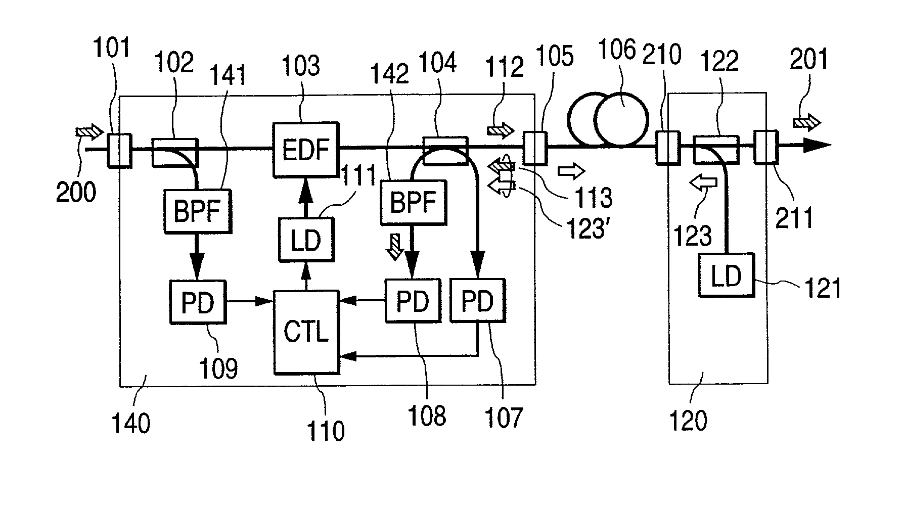
[0145] By the way, FIG. 4 shows only main portions that are directly involved in the present invention. As exemplified in the first embodiment described above, an optical amplifier is provided with the following desired control: keeping output intensity of pump wave constant; or keeping output intensity of an optical amplifier 140 constant; or controlling a signal gain of the optical amplifier 140 so that the gain is kept constant; or the like. Detailed description of those points is omitted. Similarly, in embodiments described below, only main portions directly involved in the present invention are presented.

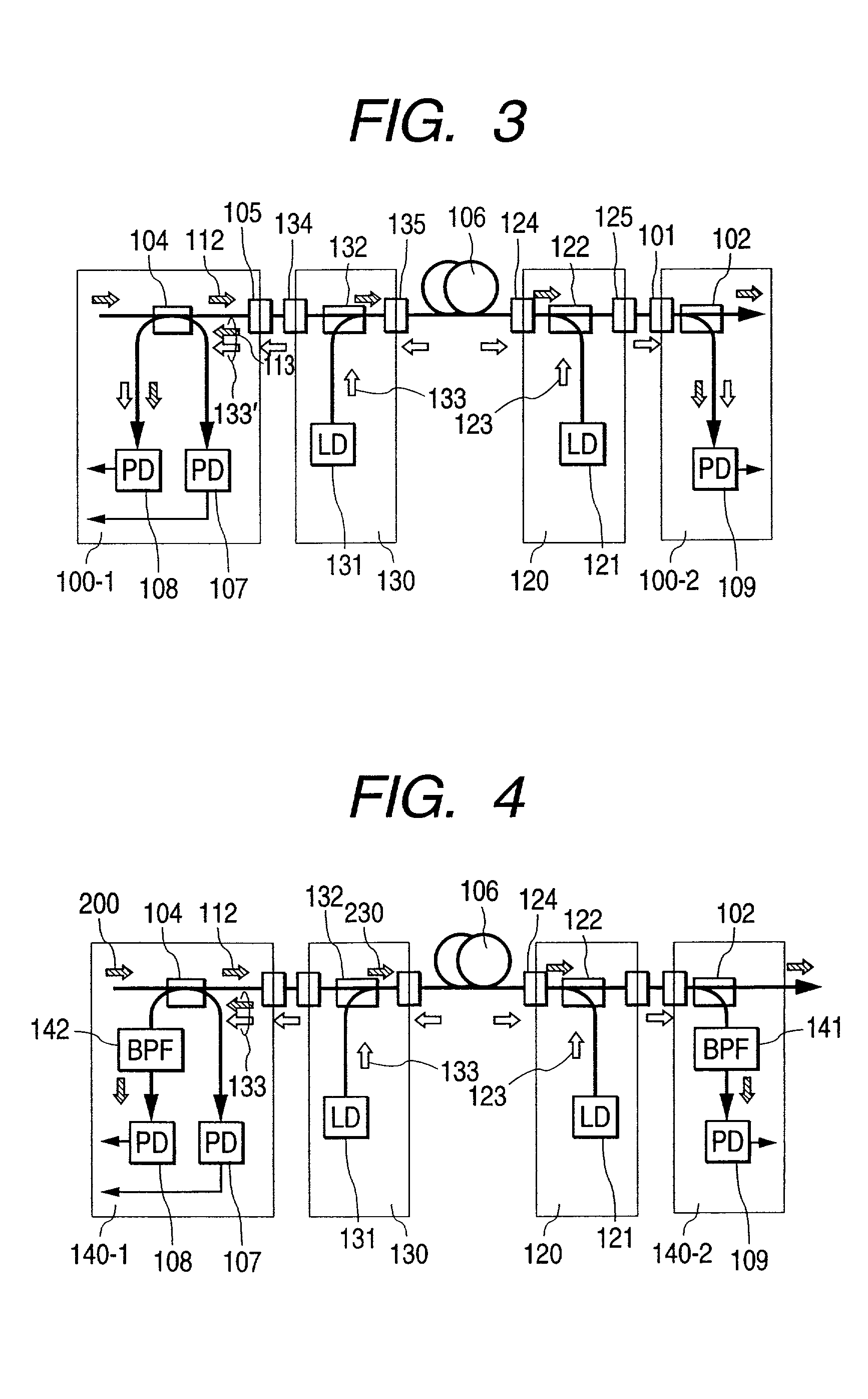
[0146] Optical signal, which has been amplified in an optical amplifier 140-1, is input to optical fiber Raman amplifier 130. The optical signal is mixed with pump wave 133, which has been output from Raman pump wave source 131, by a wavelength multiplexer 132. The optical signal is then input to an optical fiber transmission line 106.

[0147] On the other hand, pump wave 123, wh...

second embodiment

[0152] For example, in the second embodiment described above, there may be a case where either the optical amplifier 140-1 or 140-2 does not exist, or there may be a case where either the Raman amplifier 120 or 130 does not exist or both of them do not exit. Moreover, in contrast to such configurations, there may be a configuration in which another optical amplifier is added so as to form multistage connection, or a configuration in which a plurality of optical fiber transmission lines are used for repeated transmission. However, application of the present invention produces no problem. For example, even if there is no Raman amplifier, locating the Raman pump wave elimination filters 141 and 142 in the optical amplifier 140-1 and 140-2 in advance will prevent interruption circuits of the optical amplifier 140-1 and 140-2 from malfunctioning if a Raman amplifier is used in future. Furthermore, this embodiment has an advantage that a device configuration can be integrated and shared.

[...

fourth embodiment

[0159] A forth embodiment is an example that changes detecting threshold values of input and output detection circuits in response to a condition of pump wave, which is the second technical concept of the present invention described above. FIG. 7 is a diagram illustrating the present invention. This example describes that a pump wave-source current 158 from a pump wave-source current source 157 is controlled by a control circuit 110 in response to a condition of Raman pump wave.

[0160] In this example, in the control circuit 110, a switch 159 switches between reference voltage sources 153-1 and 153-2 to produce a different reference voltage in response to ON / OFF signal 160 of the Raman pump wave. As a result, a judgment threshold value is changed. An Input-light intensity signal 150 and a signal of said reference voltage value are input to a comparator 154-1. For example, it is assumed that the reference voltage source 153-1 has a high voltage value, and that the reference voltage so...


PUM

PropertyMeasurementUnit
wavelengthaaaaaaaaaa

Abstract

An object of the present invention is to prevent an interruption circuit of an optical amplifier from malfunctioning due to Raman pump wave. A typical mode of the present invention is characterized in that an pump wave elimination filter is inserted before an input-light detector and a reflected-light detector which constitute the optical amplifier. This permits only a signal component to be detected, enabling interruption operation, while eliminating a remaining component of Raman pump wave transmitted from for example a downstream of an optical fiber transmission line. In addition, a judgment threshold value for the interruption operation is changed according to ON/OFF condition of the pump wave. Or the Raman pump wave itself is used for detecting output's open.

Description

[0001] 1. Field of the Invention[0002] The present invention relates to an optical system that uses Raman pump wave. Typical examples of the optical system include an optical amplifier; a Raman pump wave emitting device, for example, a Raman pump wave emitting device for optical amplification by stimulated Raman effect in an optical fiber; and an optical repeater; or an optical system in which those devices are used.[0003] 2. Related Arts[0004] Wavelength, division multiplexing (WDM) optical-transmission method, by which a plurality of optical signals having a different wavelength one another are multiplexed in an optical fiber to transmit information, is a very effective method for increasing capacity of optical fiber communication. For the purpose of repeating / amplifying such optical signals, the following optical fiber amplifiers are used: an optical fiber amplifier doped with rare-earth elements such as EDFA (Erbium-doped Fiber Amplifier); a semiconductor optical amplifier; and ...

Claims


Application Information

Patent Timeline
Patent Type & Authority Applications(United States)
IPC IPC(8): G02F1/35H01S3/00H01S3/06H01S3/067H01S3/30
CPCH01S3/06754H01S3/094011H01S3/10015H01S3/302H04B10/2916
Inventor KIKUCHI, NOBUHIKO
Owner HITACHI LTD
Why Eureka
Try Eureka